

Simple capacitor networks
Like resistors, capacitors can also be connected to form networks. The simple basic circuits, which can in turn be interconnected to form networks of any complexity, are presented below.
1 Parallel connection of capacities
If several capacitances are connected in parallel in a circuit, they can be combined to form a total capacitance (see Figure 1).
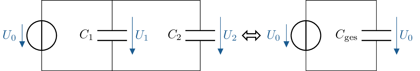
The same voltage is applied to all individual capacities:
\begin {equation*} U_0 = U_1 = U_2 \end {equation*}
The charge stored on each of the individual capacitors can be determined as follows:
\begin {equation*} Q_k = C_k \cdot U_0 \end {equation*}
The total charge \(C_\mathrm {total}\) on the equivalent circuit diagram in Figure 1 corresponds to
\begin {equation*} Q_\mathrm {ges} = C_\mathrm {ges} \cdot U_0 \end {equation*}
The total load is made up of the sum of the individual loads:
\begin {equation*} Q_\mathrm {ges} = Q_1 + Q_2 = C_1 \cdot U_0 + C_2 \cdot U_0 \end {equation*}
\begin {equation*} Q_\mathrm {ges} = (C_1 + C_2) \cdot U_0 \end {equation*}
A comparison of the quotient with the original calculation of the total charge \(Q_\mathrm {total}\) now shows:
\begin {equation*} \rightarrow C_1 + C_2 = C_\mathrm {ges} \end {equation*}
Even for any number of capacities connected in parallel, the sum of the individual capacities equals the total capacity:
Key point: Total capacity of a parallel connection
\begin {equation*} C_\mathrm {ges} = \sum _{k=1}^{n} C_k \end {equation*}
2 Series connection of capacitances
When capacitors are connected in series, the total voltage \(U_\mathrm {0}\) applied to the input terminals is divided into partial voltages \(U_k\) across the individual capacitors (Figure 2).
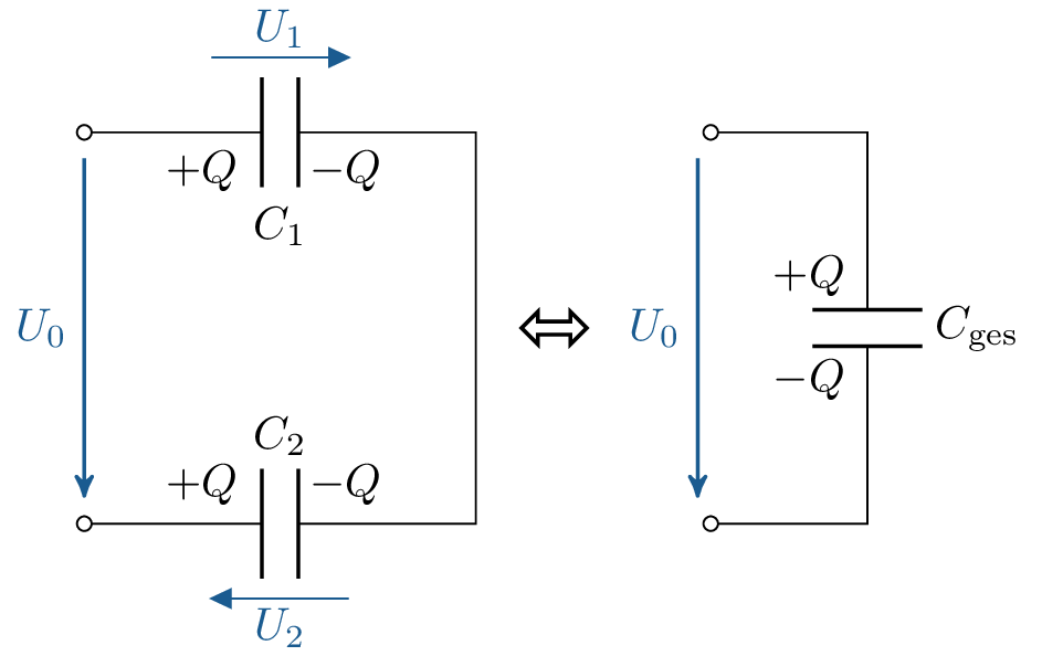
A charge of \(\pm \, Q\) is applied to the capacitor plates connected to the terminals. Both plates of the same capacitor always have charges of equal magnitude, which means that both capacitors at the terminals of the series connection have a charge of \(\pm \, Q\) on both plates. The outer plate of the next connected capacitor must have an identical charge with the opposite sign, as no charge carriers can escape or be added to the originally electrically neutral connection. Following this pattern, all capacitors in a series connection have the same charge \(Q\).
Based on the basic capacitor equation \(Q = C \cdot U\), the partial voltages across the capacitors shown in Figure 2 are:
\begin {equation*} U_1 = \frac {Q}{C_1}, U_2 = \frac {Q}{C_2} \end {equation*}
Inserted into the result of the mesh cycle of the output circuit, this gives:
\begin {equation*} U_0 = U_1 + U_2 = \left ( \frac {1}{C_1} + \frac {1}{C_2} \right ) \cdot Q \end {equation*}
The voltage \(U_0\) in the equivalent circuit diagram can be calculated as follows:
\begin {equation*} U_0 = \frac {1}{C_\mathrm {tot}} \cdot Q \end {equation*}
A comparison of ratios reveals:
\begin {equation*} \frac {1}{C_1} + \frac {1}{C_2} = \frac {1}{C_\mathrm {tot}} \end {equation*}
In general, the following applies to a series connection of any number of capacitors:
Key point: Total capacity of a series connection:
For two capacitors connected in series, the total capacitance \(C_\mathrm {total}\) can also be determined using the following expression, analogous to the parallel connection of resistors:
\begin {equation*} C_\mathrm {tot} = \frac {C_1 \cdot C_2}{C_1 + C_2} \end {equation*}
3 Voltage divider on capacitances
Similar to the voltage divider with two resistors connected in series, the ratio of the divided voltage can also be determined for two capacitors with identical charges connected in series (see Figure 3).

The voltage \(U_1\) can be determined as follows:
\begin {equation*} U_1 = \frac {Q}{C_1} \end {equation*}
The charge \(Q\) is unknown, but it is identical for both capacitors \(C_1\) and \(C_2\) as well as in the equivalent circuit at \(C_\mathrm {total}\):
\begin {equation*} Q = C_\mathrm {tot} \cdot U_0 = \frac {C_1 \cdot C_2}{C_1 + C_2} \cdot U_0 \end {equation*}
Substituting, we obtain for \(U_1\):
\begin {equation*} U_1 = \frac {1}{\cancel {C_1}} \cdot \frac {\cancel {C_1} \cdot C_2}{C_1 + C_2} \cdot U_0 = U_0 \cdot \frac {C_2}{C_1 + C_2} \end {equation*}
The voltage divider for \(U_2\) is calculated analogously:
Key point:
\begin {equation*} U_1 = \frac {C_2}{C_1 + C_2} \cdot U_0, U_2 = \frac {C_1}{C_1 + C_2} \cdot U_0 \end {equation*}
