

1 Monitoring a voltage with LEDs
The circuit shown is given; it is to be used to monitor the voltage \(U_\mathrm {a}\). \(U_\mathrm {a}\) may only lie within the following range: \(\mathrm {4.75\,V} < U_\mathrm {a} < \mathrm {5.25\,V}\). If the voltage exceeds or falls below this range, one of the LEDs should light up. Design the circuit.
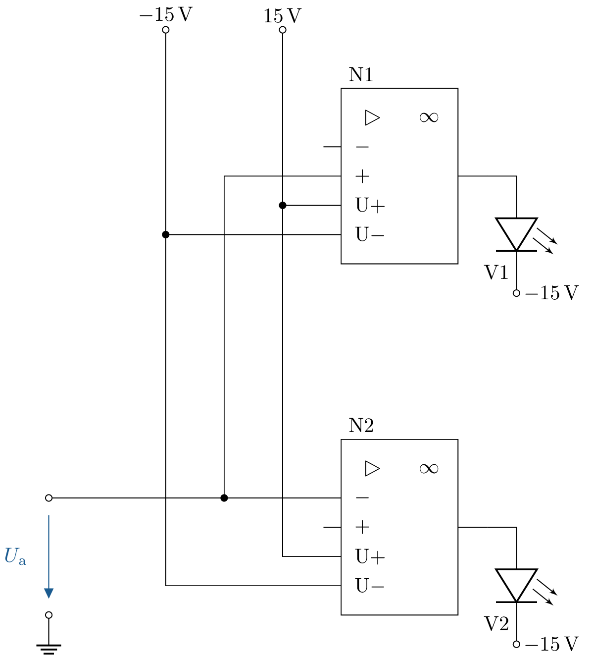
1.1 Lösung:
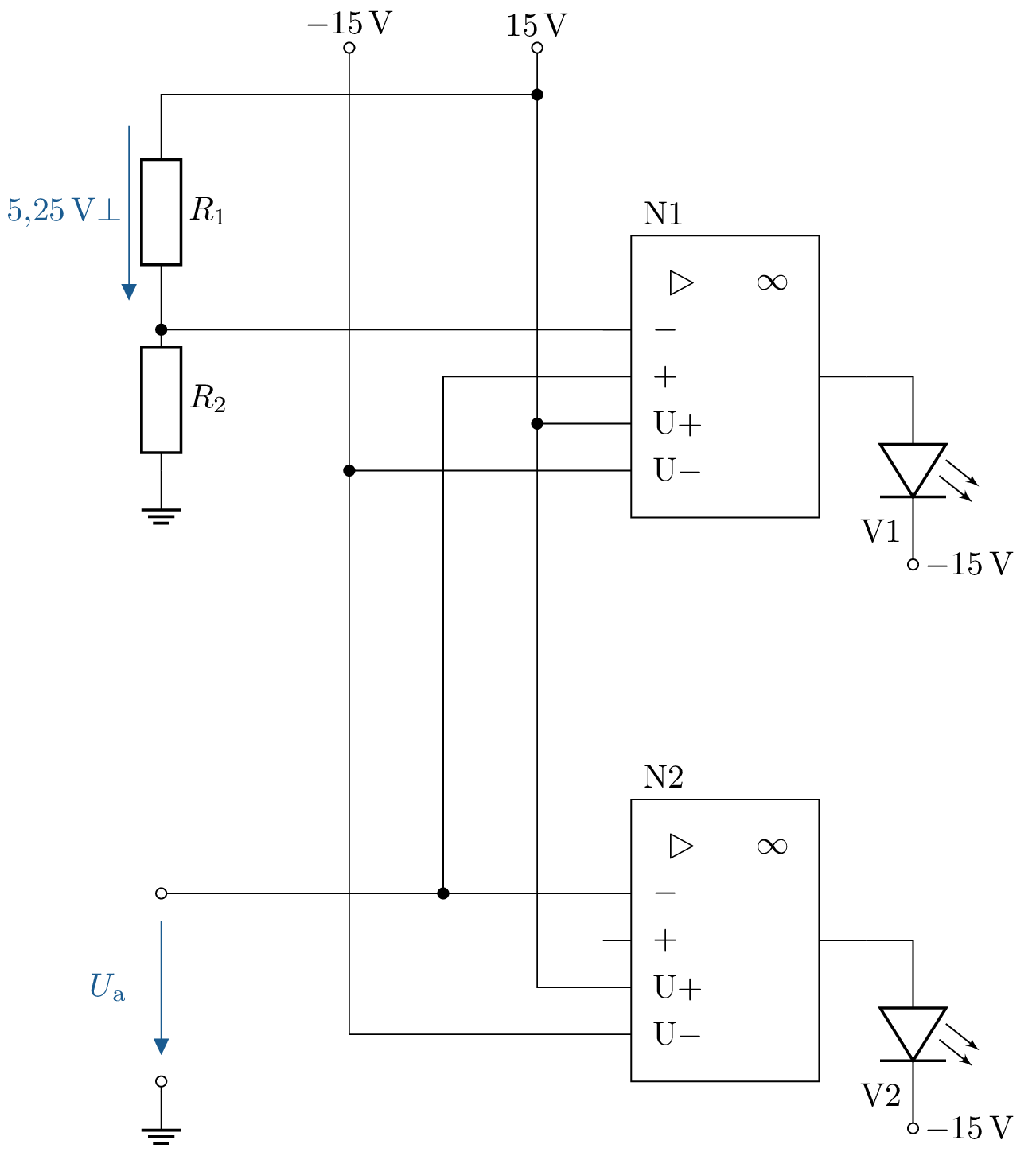
\begin {equation*} \begin {aligned} \frac {U_1}{U_0} &= \frac {R_1}{R_1 + R_2} \\ \frac {U_1 \cdot (R_1 + R_2)}{U_0} &= R_1 \\ U_1\cdot (R_1+R_2) &= R_1 \cdot U_0 \\ U_1\cdot R_1 + U_1\cdot R_2 &= R_1 \cdot U_0 \\ U_1\cdot R_1 &= R_1 \cdot U_0 - U_1\cdot R_2 \\ U_1\cdot R_2 &= R_1 \cdot (U_0 - U_1) \\ \frac {U_1 \cdot R_2}{U_0 - U_1} &= R_1 \end {aligned} \end {equation*}
\[ R_1 = 268.96 \, \Omega \]
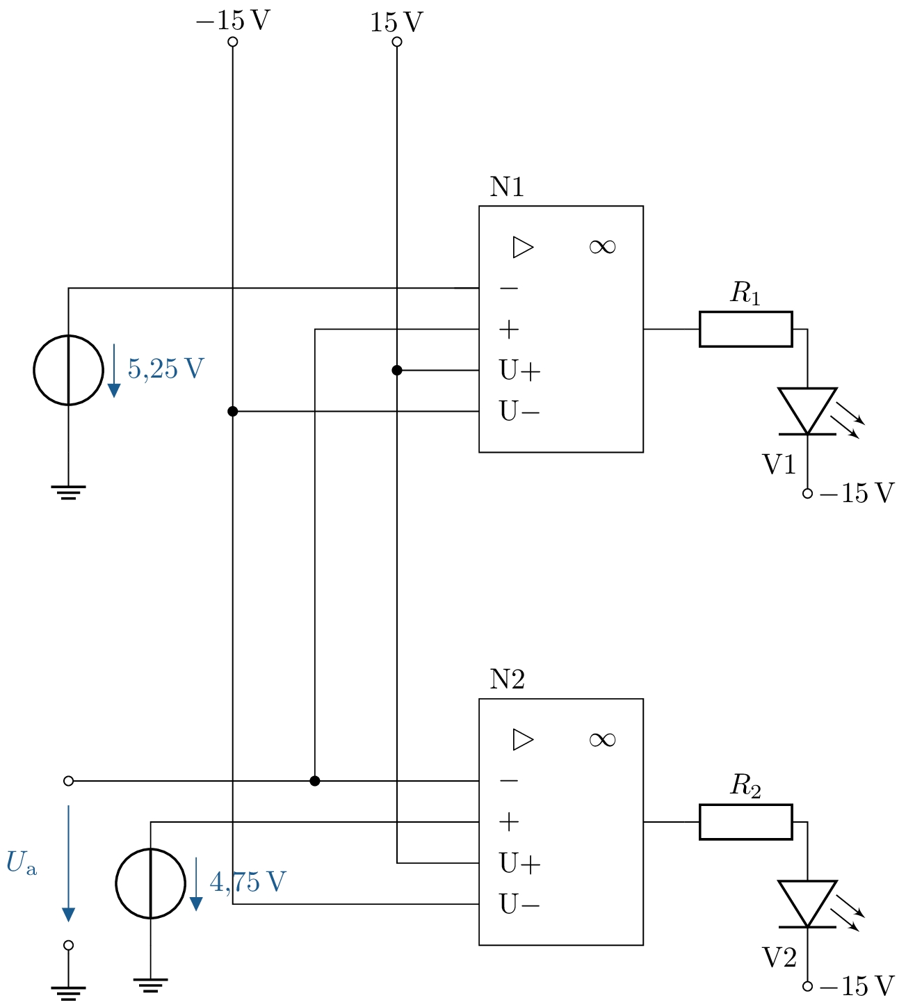
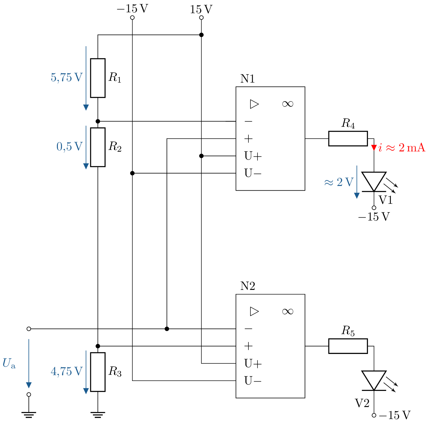
\begin {align*} R_1 &= 3.75 \,\text {k}\Omega \\ R_2 &= 500 \,\Omega \\ R_3 &= 4.75 \,\text {k}\Omega \\ R_4 &= \frac {28 \, \mathrm {V}}{20 \, \mathrm {mA}} \approx 1,4 \,\text {k}\Omega \end {align*}
See section: ?? and Table ??
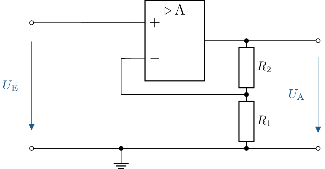
2 Resistance calculation for non-inverting amplifiers
The depicted circuit with a non-inverting amplifier is given. The resistor \(R_\mathrm {2} = 1\,\mathrm {k\Omega }\). What values must \(R_\mathrm {1}\) have so that the gain is 10, 50, and 100?
2.1 Lösung:
According to the formula for non-inverting amplifiers: \begin {align} V = 1 + \frac {R_\mathrm {1}}{R_\mathrm {2}} \end {align} Rearrange the formula according to \(R_1\): \begin {align} R_1 = R_2 \cdot (V - 1) \end {align}
- \(V = 10\) \begin {align*} R_1 = \mathrm {1\,k\Omega \cdot (10 - 1) = 9\,k\Omega } \end {align*}
- \(V = 50\) \begin {align*} R_1 = \mathrm {1\,k\Omega \cdot (50 - 1) = 49\,k\Omega } \end {align*}
- \(V = 100\) \begin {align*} R_1 = \mathrm {1\,k\Omega \cdot (100 - 1) = 99\,k\Omega } \end {align*}
See section: ?? and Table ??
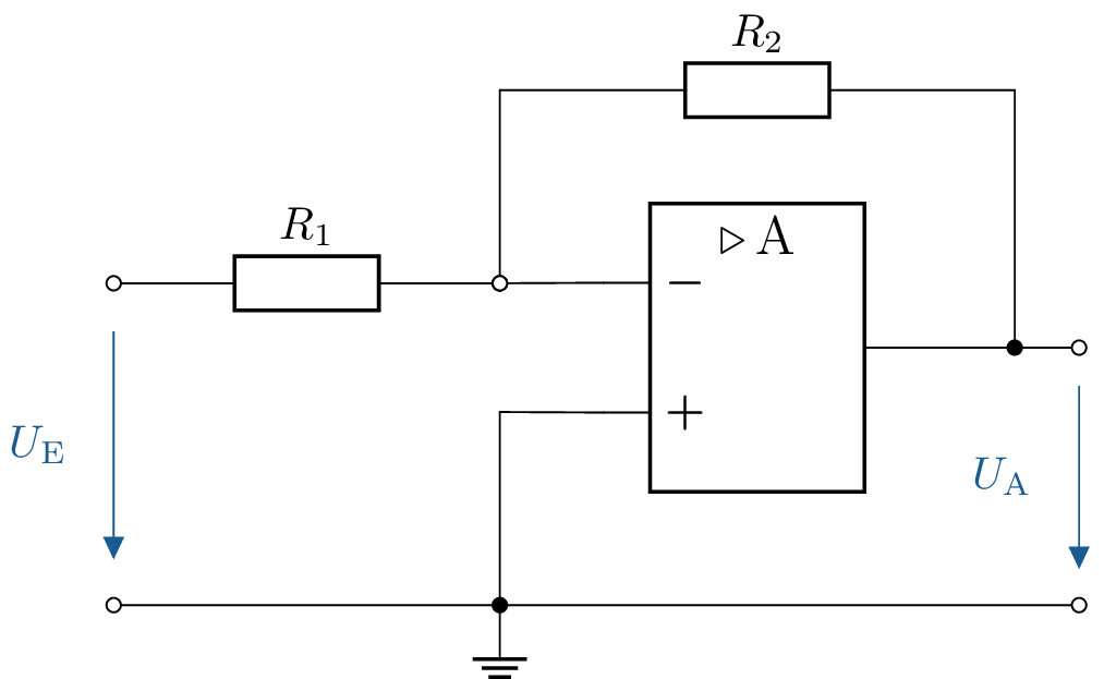
3 Resistance calculation for inverting amplifier
The depicted circuit with an inverting amplifier is given. The resistor \(R_\mathrm {2} = 1\,\mathrm {k\Omega }\). What values must \(R_\mathrm {1}\) have so that the gain is -10, -50, and -100?
3.1 Lösung:
According to the formula for inverting amplifiers: \begin {align} V = - \frac {R_2}{R_1} \end {align} Rearrange formula according to \(R_\mathrm {1}\): \begin {align} R_1 = - \frac {R_2}{V} \end {align}
- \(V = - 10\) \begin {align*} R_1 =\mathrm {- \frac {1\,k\Omega }{- 10} = 100\,\Omega } \end {align*}
- \(V = - 50\) \begin {align*} R_1 =\mathrm {- \frac {1\,k\Omega }{- 50} = 20\,\Omega } \end {align*}
- \(V = - 100\) \begin {align*} R_1 =\mathrm {- \frac {1\,k\Omega }{- 100} = 10\,\Omega } \end {align*}
See section: ?? and Table ??
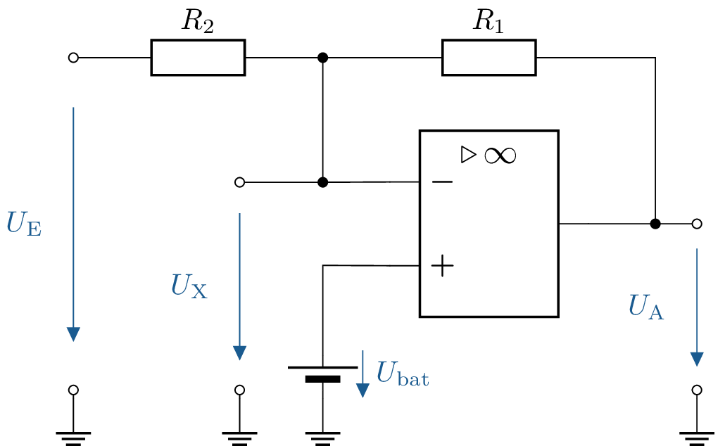
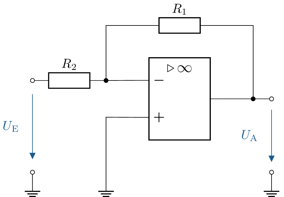
4 Calculation of the output voltage of an operational amplifier circuit with two inputs
The depicted circuit with an ideal operational amplifier is given. The resistors are \(R_\mathrm {1} = \mathrm {100\,k\Omega }\) and \(R_2=\mathrm {10\,k\Omega }\). The supply voltage is \(\mathrm {\pm 15\,V}\).
- Determine the output voltage \(U_\mathrm {A}\) bei \(U_\mathrm {E}=2\,\mathrm {mV}\) and \(U_\mathrm {bat} = \mathrm {0\,V}\)
- Determine the output voltage \(U_\mathrm {A}\) bei \(U_\mathrm {E}=20\,\mathrm {mV}\) and \(U_\mathrm {bat}=\mathrm {0\,V}\)
4.1 Lösung:
Calculate reinforcement: \begin {align*} V =\mathrm {- \frac {100\,k\Omega }{10\,k\Omega } = -10} \end {align*}
Formula for amplification: \begin {align} V = \frac {U_\mathrm {A}}{U_\mathrm {E}} \end {align} Rearrange formula according to \(U_\mathrm {A}\): \begin {align*} U_\mathrm {A} = V \cdot U_\mathrm {E} \end {align*}
- \begin {align*} U_\mathrm {A} = \mathrm {-10 \cdot 2\,mV = -20\,mV} \end {align*}
- \begin {align*} U_\mathrm {A} = \mathrm {-10 \cdot 20\,mV = -200\,mV} \end {align*}
See section: ?? and Table ??
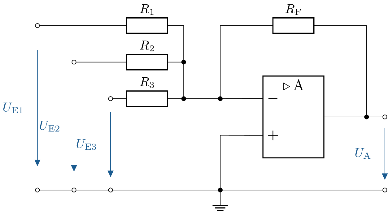
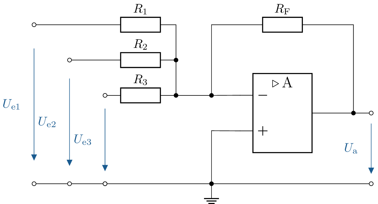
5 Calculate the output voltage of an operational amplifier with multiple inputs
The depicted circuit with an ideal operational amplifier is given. The supply voltage is \(\mathrm {\pm 15\,V}\).
- All resistors are equal: \(R_1 = R_2 = R_3 = R_\mathrm {F} = 10\,\mathrm {k\Omega }\). The input voltages are \(U_\mathrm {E1} = \mathrm {1\,V}\), \(U_\mathrm {E2} = \mathrm {2\,V}\), \(U_\mathrm {E3} = \mathrm {3\,V}\). What is the output voltage \(U_\mathrm {A}\)?
- The input voltages remain the same, but the resistors are now \(R_\mathrm {F} = \mathrm {10\,k\Omega }\), \(R_\mathrm {1} = \mathrm {2\,k\Omega }\), \(R_\mathrm {2} = \mathrm {5\,k\Omega }\), \(R_\mathrm {3} = \mathrm {10\,k\Omega }\). What is the output voltage \(U_\mathrm {A}\)?
- The input voltages remain the same, but the resistors are now \(R_\mathrm {F} = \mathrm {10\,k\Omega }\), \(R_\mathrm {1} = \mathrm {10\,k\Omega }\), \(R_\mathrm {2} = \mathrm {5\,k\Omega }\), \(R_\mathrm {3} = \mathrm {2\,k\Omega }\). What is the output voltage \(U_\mathrm {A}\)?
5.1 Lösung:
Formula: \begin {align} U_\mathrm {A} = - (U_\mathrm {E1} \cdot \frac {R_\mathrm {F}}{R_1} + U_\mathrm {{E2}} \cdot \frac {R_\mathrm {F}}{R_2} + U_\mathrm {E3} \cdot \frac {R_\mathrm {F}}{R_3}) \end {align}
- \begin {align*} U_\mathrm {A} =\mathrm {- (1\,V \cdot \frac {10\,k\Omega }{10\,k\Omega } + 2\,V \cdot \frac {10\,k\Omega }{10\,k\Omega } + 3\,V \cdot \frac {10\,k\Omega }{10\,k\Omega }) = -6\,V} \end {align*}
- \begin {align*} U_\mathrm {A} =\mathrm { - (1\,V \cdot \frac {10\,k\Omega }{2\,k\Omega } + 2\,V \cdot \frac {10\,k\Omega }{5\,k\Omega } + 3\,V \cdot \frac {10\,k\Omega }{10\,k\Omega }) = -12\,V} \end {align*}
-
\begin {align*} U_\mathrm {A} =\mathrm { - (1\,V \cdot \frac {10\,k\Omega }{10\,k\Omega } + 2\,V \cdot \frac {10\,k\Omega }{5\,k\Omega } + 3\,V \cdot \frac {10\,k\Omega }{2\,k\Omega }) = -20\,V} \end {align*}
Note: \(-20\,\mathrm {V}\) is not possible because the supply voltage is \(\mathrm {\pm 15\,V}\). This means the lowest possible value is \(-15\,V\).
See section: ?? and Table ??
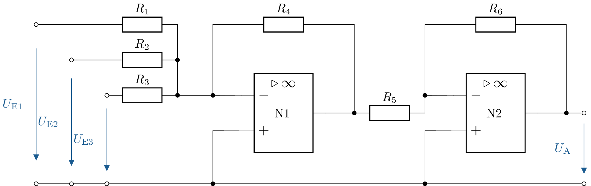
6 Calculation of the output voltage of a two-stage operational amplifier circuit
Calculate \(U_\mathrm {A}\) with the following values:
\(R_1 = \mathrm {10\,k\Omega }\), \(R_2 = \mathrm {20\,k\Omega }\), \(R_3 = \mathrm {30\,k\Omega }\), \(R_4 = \mathrm {10\,k\Omega }\), \(R_5 = \mathrm {20\,k\Omega }\)
6.1 Lösung:
Formula: \begin {equation} U_\mathrm {N1} = - \left ( \frac {R_\mathrm {N}}{R_\mathrm {1}} U_\mathrm {E1} + \frac {R_\mathrm {N}}{R_2} U_\mathrm {E2} + \frac {R_\mathrm {N}}{R_\mathrm {3}} U_\mathrm {E3} \right ) \end {equation} \begin {equation} U_\mathrm {A} = -\frac {R_\mathrm {6}}{R_\mathrm {5}} U_\mathrm {N1} \end {equation}
Calculation:
Calculation of \(U_\mathrm {N1}\) \begin {align*} U_\mathrm {N1} &= - \left ( \frac {10\,\mathrm {k}\Omega }{10\,\mathrm {k}\Omega } U_\mathrm {E1} + \frac {10\,\mathrm {k}\Omega }{20\,\mathrm {k}\Omega } U_\mathrm {E2} + \frac {10\,\mathrm {k}\Omega }{30\,\mathrm {k}\Omega } U_\mathrm {E3} \right ) \\ &= - \left ( U_\mathrm {E1} + 0,5 U_\mathrm {E2} + \frac {1}{3} U_\mathrm {E3} \right ) \end {align*}
Calculation of \(U_\mathrm {A}\) \begin {align*} U_\mathrm {A} &= -2 \cdot U_\mathrm {N1} \\ &= -2 \left ( - \left ( U_\mathrm {E1} + 0,5 U_\mathrm {E2} + \frac {1}{3} U_\mathrm {E3} \right ) \right ) \\ &= 2 \left ( U_\mathrm {E1} + 0,5 U_\mathrm {E2} + \frac {1}{3} U_\mathrm {E3} \right ) \end {align*}
The output voltage \(U_\mathrm {A}\) is therefore: \begin {align*} U_\mathrm {A} &= 2 U_\mathrm {E1} + U_\mathrm {E2} + \frac {2}{3} U_\mathrm {E3} \end {align*}
See section: ?? and Table ??
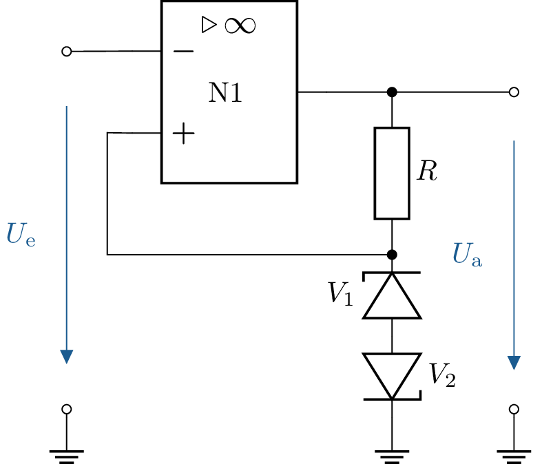
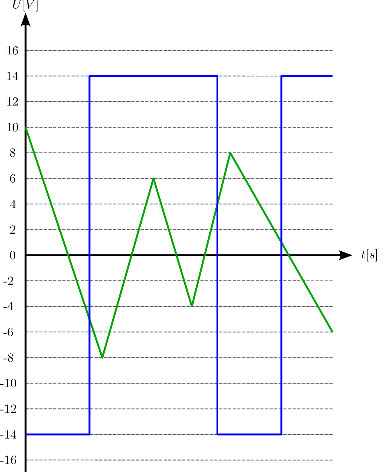
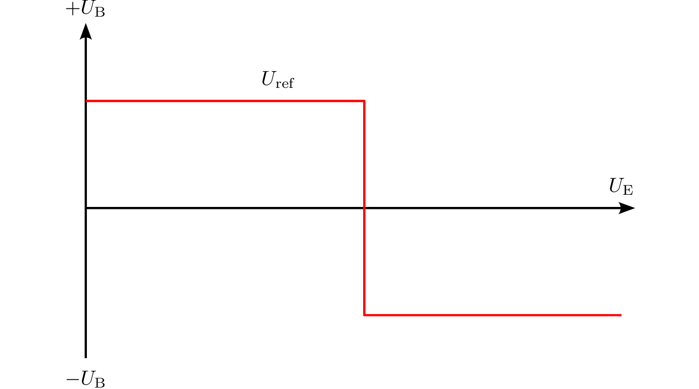
7 Dimensioning of a comparator circuit with diode
Dimension the circuitry of the comparator so that the transfer behaviour outlined below is achieved. The forward voltage of the diode is assumed to be \(U_\mathrm {D} = \mathrm {0,7\,V}\). The maximum power dissipation of the resistor is 1/4 W.
7.1 Lösung:
Formula: \begin {equation} P_\mathrm {R} = \frac {U_\mathrm {R}^2}{R} \end {equation}
Calculation:
Voltage across the resistor \(R\): \begin {align*} U_\mathrm {R} &= U_\mathrm {a} - U_\mathrm {D} \\ &= 14\,\mathrm {V} - 0,7\,\mathrm {V} \\ &= 13,3\,\mathrm {V} \end {align*}
Calculation of resistance \(R\): \begin {align*} P_\mathrm {R} &= \frac {U_\mathrm {R}^2}{R} \leq \frac {1}{4}\,\mathrm {W} \\ R &= \frac {U_R^2}{P_{\text {max}}} \\ &= \frac {(13,3\,\mathrm {V})^2}{0,25\,\mathrm {W}} \\ &= \frac {176,89\,\mathrm {V}^2}{0,25\,\mathrm {W}} \\ &= 707,56\,\Omega \end {align*}
Formed resistance value: \begin {align*} R &= 710\,\Omega \end {align*}
Checking the power loss: \begin {align*} P_\mathrm {R} &= \frac {(13,3\,\mathrm {V})^2}{710\,\Omega } \approx 0,25\,\mathrm {W} \end {align*}
The resistance \(R\) should have the value: \begin {align*} R &= 710\,\Omega \end {align*}
In order not to exceed the maximum power dissipation and to ensure the desired transmission behaviour. See section: ?? and Table ??
8 Description of the ideal characteristics of an operational amplifier
Describe the following characteristics of an ideal operational amplifier:
- Input resistance
- Output resistance
- Differential amplification
- Input offset voltage
8.1 Lösung:
- Input resistance: infinite, to minimize loading on the voltage source
- Output resistance: \(0\,\Omega \), so that the op-amp can deliver as much power as possible
- Differential gain: infinite, to amplify small signals
- Input offset voltage: \(0\,\mathrm {V}\), so that the op-amp produces no output voltage when there is no input signal
See section: ??
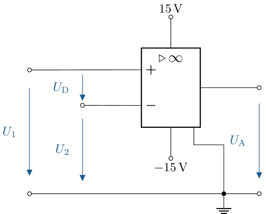
9 Determining the output voltage of a comparator
The depicted comparator is given. The voltage \(U_\mathrm {1}= \mathrm {8.25\,V}\) is constant. What is the output voltage for \(U_2 = \mathrm {0\,V; 4\,V; 8\,V; 8.2\,V; 8.249\,V; 8.251\,V; 8.3\,V; 10\,V}\)?
9.1 Lösung:
Exploitation of the mesh rule states: \begin {align*} -U_1 + U_2 + U_D &= 0 \\ U_\mathrm {D} &= U_1 - U_2 \end {align*}
- \(U_2 = 0\,V\) \begin {align*} U_\mathrm {D} &= \mathrm { 8,25\,V - 0\,V = 8,25\,V}\\ U_\mathrm {A} &= \mathrm {13,5\,V} \end {align*}
- \(U_2 = 4\,V\) \begin {align*} U_\mathrm {D} &= \mathrm { 8,25\,V - 4\,V = 4,25\,V}\\ U_\mathrm {A} &= \mathrm {13,5\,V} \end {align*}
- \(U_2 = 8\,V\) \begin {align*} U_\mathrm {D} &= \mathrm { 8,25\,V - 8\,V = 0,25\,V}\\ U_\mathrm {A} &= \mathrm {13,5\,V} \end {align*}
- \(U_2 = 8,2\,V\) \begin {align*} U_\mathrm {D} &= \mathrm { 8,25\,V - 8,2\,V = 0,05\,V}\\ U_\mathrm {A} &= \mathrm {8\,V} \end {align*}
- \(U_2 = 8,249\,V\) \begin {align*} U_\mathrm {D} &= \mathrm { 8,25\,V - 8,249\,V = 1\,mV}\\ U_\mathrm {A} &= \mathrm {4\,V} \end {align*}
- \(U_2 = 8,251\,V\) \begin {align*} U_\mathrm {D} &= \mathrm { 8,25\,V - 8,251\,V = -1\,mV}\\ U_\mathrm {A} &= \mathrm {-4\,V} \end {align*}
- \(U_2 = 8,3\,V\) \begin {align*} U_\mathrm {D} &= \mathrm { 8,25\,V - 8,3\,V = -0,05\,V}\\ U_\mathrm {A} &= \mathrm {-8\,V} \end {align*}
- \(U_2 = 10\,V\) \begin {align*} U_\mathrm {D} &= \mathrm { 8,25\,V - 10\,V = -1,75\,V}\\ U_\mathrm {A} &= \mathrm {-13,5\,V} \end {align*}
See section: ?? and Table ??
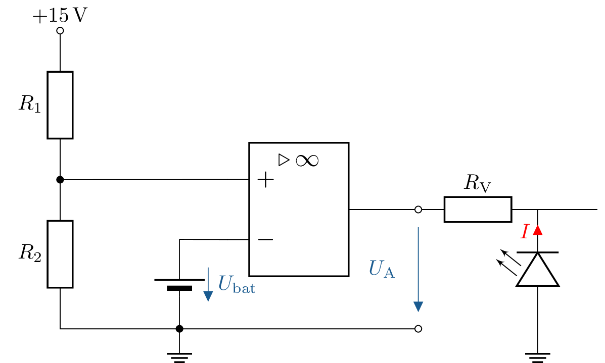
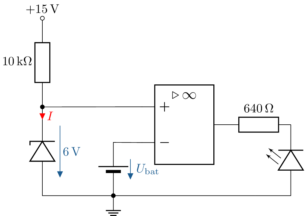
10 Calculate comparator circuit for battery monitoring
A comparator is to be used to monitor the charge status of a battery. The comparator should switch over when the battery voltage \(U_\mathrm {bat}\) falls below \(6\,\mathrm {V}\). The resistor \(R_1\) is \(10\,\mathrm {k\Omega }\). The operating voltage of the comparator is \(\pm 15\,\mathrm {V}\).
- What value must the resistor \(R_2\) have?
- To indicate the charge level, an LED is to be used. Extend the circuit to include a charge indicator using an LED.
- A maximum current of 20 mA may flow through the LED with a forward voltage of 2.2 V. What value must the series resistor have?
- The voltage at the voltage divider depends on the supply voltage. What other suitable components exist for generating the reference voltage? Name and draw an example.

10.1 Lösung:
-
Calculation of resistance \(R_2\)
The comparator should switch when the battery voltage \(U_{\text {bat}}\) falls below \(6\,\mathrm {V}\). The ratio of resistors \(R_1\) and \(R_2\) in the voltage divider must be selected so that the reference voltage \(U_{\text {ref}} = 6\,\mathrm {V}\) is applied to the non-inverting input: \[ U_{\text {ref}} = \frac {R_2}{R_1 + R_2} \cdot U_\mathrm {B} \] with \(U_\mathrm {B} = 15\,\mathrm {V}\) and \(R_1 = 10\,\mathrm {k}\Omega \). Insert: \[ 6\,\mathrm {V} = \frac {R_2}{10\,\mathrm {k}\Omega + R_2} \cdot 15\,\mathrm {V} \] Convert to \(R_2\): \[ R_2 = \frac {6\,\mathrm {V} \cdot 10\,\mathrm {k}\Omega }{15\,\mathrm {V} - 6\,\mathrm {V}} = 6,66\,\mathrm {k}\Omega \]
-
Adding an LED display to the circuit:
The LED should indicate when the battery voltage falls below \(6\,\mathrm {V}\). To do this, the LED is connected to the output of the comparator with a series resistor \(R_V\).
-
Switching behaviour of the circuit:
-
Battery empty (\(U_{\text {bat}} = 5\,\mathrm {V}\)): \begin {align*} U_+ &= 6\,\mathrm {V} - U_{\text {bat}} \\ U_+ &= 6\,\mathrm {V} - 5\,\mathrm {V} = 1\,\mathrm {V} \end {align*}
Since \(U_+ < U_{\text {ref}}\), the comparator switches: \[ U_\mathrm {A} = -15\,\mathrm {V} \] The LED is lit.
-
Full battery (\(U_{\text {bat}} = 7\,\mathrm {V}\)): \begin {align*} U_+ &= 6\,\mathrm {V} - U_{\text {bat}} \\ U_+ &= 6\,\mathrm {V} - 7\,\mathrm {V} = -1\,\mathrm {V} \end {align*}
Since \(U_+ > U_{\text {ref}}\), the comparator switches: \[ U_\mathrm {A} = 15\,\mathrm {V} \] The LED remains off.
![PIC]()
-
-
Dimensioning of the series resistor \(R_\mathrm {V}\)
Given:
- LED forward voltage: \(U_\mathrm {F} = 2,2\,\mathrm {V}\)
- Current through the LED: \(I_\mathrm {F} = 20\,\mathrm {mA}\)
- Output voltage of the comparator: \(U_\mathrm {A} = 15\,\mathrm {V}\)
The series resistor\(R_\mathrm {V}\) is calculated from: \[ R_\mathrm {V} = \frac {U_\mathrm {A} - U_\mathrm {F}}{I_\mathrm {F}} \] Applying the values: \[ R_\mathrm {V} = \frac {15\,\mathrm {V} - 2,2\,\mathrm {V}}{20\,\mathrm {mA}} = \frac {13,8\,\mathrm {V}}{0,02\,\mathrm {A}} = 690\,\Omega \]
![PIC]()
![PIC]()
-
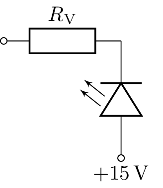
Alternative voltage reference:
Since the voltage of the voltage divider depends on the operating voltage, a Zener diode could be used as a reference element. A Zener diode provides a constant reference voltage regardless of fluctuations in the supply voltage.
-
Example circuit:
- The Zener diode is connected to the operating voltage \(+15\,\mathrm {V}\) with a series resistor.
- The reference voltage is tapped directly from the cathode of the Zener diode.

See section: ?? and table ??
11 Circuit design of an operational amplifier with two input signals
The following functional relationship exists between the output voltage \(U_\mathrm {a}\) and the input voltages \(U_\mathrm {1}\) and \(U_\mathrm {2}\): \(U_\mathrm {a} = -5 \ U_\mathrm {1} - 0.8 \ U_\mathrm {2}\).
Design a circuit using operational amplifier(s) and resistors to realize this functional relationship. Assume the operational amplifiers are ideal. Specify the values of the resistors used!
11.1 Lösung:
The given functional relationship between the output voltage \(U_\mathrm {a}\) and the input voltages \(U_1\) and \(U_2\) is: \( U_\mathrm {a} = -5 U_1 - 0,8 U_2 \)
1. Circuit description
To implement this relationship, we use a summing circuit with an inverting operational amplifier. The output voltage of the inverting summing amplifier is: \( U_\mathrm {a} = -\left ( \frac {R_\mathrm {F}}{R_1} U_1 + \frac {R_\mathrm {F}}{R_2} U_2 \right ) \) Comparison with the target: \( - \left ( \frac {R_\mathrm {F}}{R_1} \right ) = -5 \Rightarrow \frac {R_\mathrm {F}}{R_1} = 5 \) \( - \left ( \frac {R_\mathrm {F}}{R_2} \right ) = -0,8 \Rightarrow \frac {R_\mathrm {F}}{R_2} = 0,8 \)
2. Selection of resistance values
We set \(R_\mathrm {F} = 10\,\mathrm {k}\Omega \) (typical value in the range 1–100 k\(\Omega \)):
- Calculation of \(R_1\): \( \frac {R_\mathrm {F}}{R_1} = 5 \Rightarrow R_1 = \frac {R_\mathrm {F}}{5} = \frac {10\,\mathrm {k}\Omega }{5} = 2\,\mathrm {k}\Omega \)
- Calculation of \(R_2\): \( \frac {R_\mathrm {F}}{R_2} = 0,8 \Rightarrow R_2 = \frac {R_\mathrm {F}}{0,8} = \frac {10\,\mathrm {k}\Omega }{0,8} = 12,5\,\mathrm {k}\Omega \)
3. Implementation of the circuit
The resistors used: \begin {align*} R_\mathrm {F} &= 10\,\mathrm {k}\Omega \\ R_1 &= 2\,\mathrm {k}\Omega \\ R_2 &= 12,5\,\mathrm {k}\Omega \end {align*}
4. Circuit diagram of the implemented circuit
The circuit consists of an operational amplifier whose inverting input is connected to resistors \(R_1\) and \(R_2\), which feed in input voltages \(U_1\) and \(U_2\). The non-inverting input is connected to ground.
Summary:
The desired functional equation \(U_\mathrm {a} = -5 U_1 - 0.8 U_2\) is realised using the circuit described and the calculated resistance values. See section: ?? and Table ??
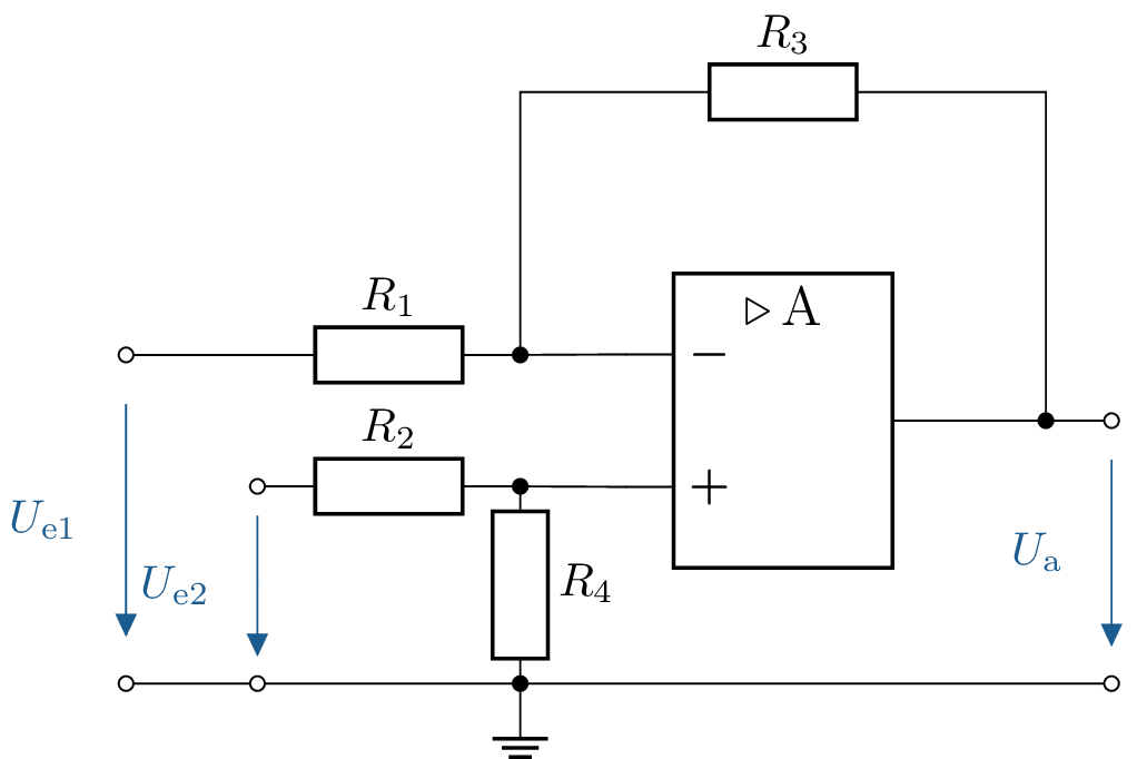
12 Design of an amplifier circuit with different input gains
The following functional relationship exists between the output voltage \(U_\mathrm {a}\) and the input voltages \(U_\mathrm {1}\) and \(U_\mathrm {2}\): \(U_\mathrm {a} = 2 \ U_\mathrm {1} - 0.5 \ U_\mathrm {2}\).
Design a circuit using operational amplifier(s) and resistors to realize this functional relationship. Assume the operational amplifiers are ideal. Specify the values of the resistors used! Typical resistor values for op-amp circuits are in the range of \(\mathrm {1\ to\ 100\,k\Omega }\).
12.1 Lösung:
The functional relationship between the output voltage \( U_a \) and the input voltages \( U_{e1} \) and \( U_{e2} \) is as follows: \[ U_\mathrm {a} = 2 U_\mathrm {e1} - 0{,}5 U_\mathrm {e2} \]
1. General formula for the output voltage of a subtractor: \[ U_\mathrm {a} = U_\mathrm {e2} \cdot \frac {R_1 + R_3}{R_2 + R_4} \cdot \frac {R_4}{R_1} - U_\mathrm {e1} \cdot \frac {R_3}{R_1} \] Comparing with the specification \( U_\mathrm {a} = 2 U_\mathrm {e1} - 0.5 U_\mathrm {e2} \) gives
the following conditions:
- Amplification factor for \( U_\mathrm {e1} \): \( \frac {R_3}{R_1} = 0.5 \)
- Amplification factor for \( U_\mathrm {e2} \): \( \frac {R_1 + R_3}{R_2 + R_4} \cdot \frac {R_4}{R_1} = 2 \)
2. Procedure:
- Set \( R_3 = 1\,\mathrm {k}\Omega \) (typical value).
- Calculate the remaining resistances..
3. Calculation of resistances:
Calculation of \( R_1 \) (from \( \frac {R_3}{R_1} = 0{,}5 \)): \[ \frac {R_3}{R_1} = 0{,}5 \Rightarrow R_1 = \frac {R_3}{0{,}5} = \frac {1\,\mathrm {k}\Omega }{0{,}5} = 2\,\mathrm {k}\Omega \]
Calculation of\( R_2 \) and \( R_4 \) (from \( \frac {R_1 + R_3}{R_2 + R_4} \cdot \frac {R_4}{R_1} = 2 \)): Set \( R_4 = 1\,\mathrm {k}\Omega \): \[ \frac {R_1 + R_3}{R_2 + R_4} \cdot \frac {R_4}{R_1} = 2 \Rightarrow \frac {3\,\mathrm {k}\Omega }{R_2 + 1\,\mathrm {k}\Omega } \cdot \frac {1\,\mathrm {k}\Omega }{2\,\mathrm {k}\Omega } = 2 \] Multiply both sides: \[ \frac {3}{2} = 2 \cdot (R_2 + 1\,\mathrm {k}\Omega ) \] Convert to \( R_2 \): \[ R_2^2 + R_2 - \frac {3}{2} = 0 \]
4. Solution using the PQ formula:
The quadratic equation has the form: \[ R_2^2 + p \cdot R_2 + q = 0 \text {mit} p = 1, \, q = -\frac {3}{2} \] PQ formula: \[ R_2 = -\frac {p}{2} \pm \sqrt {\left ( \frac {p}{2} \right )^2 - q} \] Applying the values: \[ R_2 = -\frac {1}{2} \pm \sqrt {\left ( \frac {1}{2} \right )^2 - \left ( -\frac {3}{2} \right )} = -\frac {1}{2} \pm \sqrt {\frac {1}{4} + \frac {3}{2}} \] \[ R_2 = -\frac {1}{2} \pm \sqrt {\frac {7}{4}} = -\frac {1}{2} \pm \frac {\sqrt {7}}{2} \] Since \( R_2 \) must be positive: \[ R_2 = -\frac {1}{2} + \frac {\sqrt {7}}{2} \approx 1{,}82\,\mathrm {k}\Omega \]
5. Result of the resistance: \begin {align*} R_1 &= 2\,\mathrm {k}\Omega \\ R_2 &= 1{,}82\,\mathrm {k}\Omega \\ R_3 &= 1\,\mathrm {k}\Omega \\ R_4 &= 1\,\mathrm {k}\Omega \end {align*}
See section: ?? and Table ??
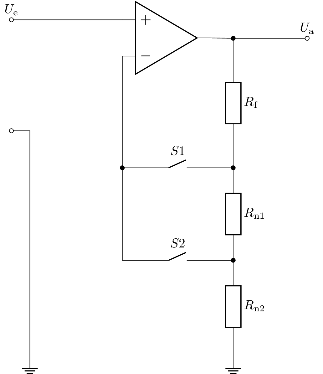
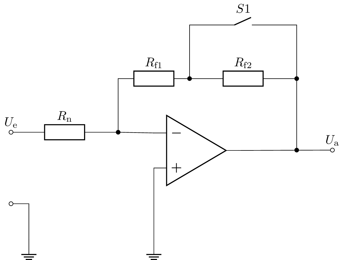
13 Gain adjustment with switchable resistors
To adjust the amplification of an operational amplifier, switches can be used to turn various resistors on and off. Calculate the operational amplifier circuits below depending on the switch positions S!
- For the circuit in Figure 1 (4 switch positions)
- For the circuit in Figure 2 (2 switch positions)
13.1 Lösung:
-
Non-inverting amplifier The gain can be changed using two switches (S1 and S2), resulting in four possible combinations:
Case 1 (S1 closed, S2 open): In this state, resistors \(R_\mathrm {n1}\) and \(R_\mathrm {n2}\) form a series connection. The total gain is therefore: \[ V = 1 + \frac {R_\mathrm {f}}{R_\mathrm {n1} + R_\mathrm {n2}} \]
Case 2 (S1 open, S2 closed): Here, resistor \(R_\mathrm {f}\) and \(R_\mathrm {n1}\) are in series. This series combination, together with resistor \(R_\mathrm {n2}\), forms the feedback loop. The gain is therefore: \[ V = 1 + \frac {R_\mathrm {f} + R_\mathrm {n1}}{R_\mathrm {n2}} \]
Case 3 (S1 and S2 closed): With both switches closed, resistor \(R_\mathrm {n1}\) is shorted and thus not considered. The gain is: \[ V = 1 + \frac {R_\mathrm {f}}{R_\mathrm {n2}} \]
Case 4 (S1 and S2 open): If both switches are open, the feedback path is missing completely, so the gain is theoretically infinite: \[ V = \infty \]
-
Inverting amplifier Case 1 (S1 open): If \(R_\mathrm {f1}\) and \(R_\mathrm {f2}\) are in series, this results in more feedback and thus higher gain. The gain is calculated as: \[ V = -\frac {R_\mathrm {f1} + R_\mathrm {f2}}{R_\mathrm {n}} \]
Case 2 (S1 closed, S2 open): In this state, resistor \(R_\mathrm {f2}\) is shorted by the closed switch and not considered. The gain is reduced to: \[ V = -\frac {R_\mathrm {f1}}{R_\mathrm {n}} \]
See section: ?? and Table ??
14 Calculation of the output voltage with multiple input voltages
The circuit shown with an ideal operational amplifier is given. The operating voltage is \(\pm 15\,\mathrm {V}\).
- All resistors are equal, with \(R_1 = R_2 = R_3 = R_\mathrm {F} = \mathrm {1\,k\Omega }\). The input voltages are \(U_\mathrm {E1} = \mathrm {1\,V}\), \(U_\mathrm {E2} = \mathrm {2\,V}\), \(U_\mathrm {E3} = \mathrm {3\,V}\). What is the output voltage \(U_\mathrm {A}\)?
- The input voltages remain the same, but the resistors are now \(R_\mathrm {F} = \mathrm {10\,k\Omega }\), \(R_1=\mathrm {2\,k\Omega }\), \(R_2=\mathrm {5\,k\Omega }\), \(R_3=\mathrm {10\,k\Omega }\). What is the output voltage \(U_\mathrm {A}\)?
- The input voltages remain the same, but the resistors are now \(R_\mathrm {F} = \mathrm {10\,k\Omega }\), \(R_1 = \mathrm {10\,k\Omega }\), \(R_2 = \mathrm {5\,k\Omega }\), \(R_3 = \mathrm {2\,k\Omega }\). What is the output voltage \(U_\mathrm {A}\)?
14.1 Lösung:
Given is a summing circuit with an ideal operational amplifier and an operating voltage of \(\pm 15\,\mathrm {V}\).
The general formula for the output voltage is: \[ U_\mathrm {A} = -\left ( U_\mathrm {E1} \cdot \frac {R_\mathrm {F}}{R_1} + U_\mathrm {E2} \cdot \frac {R_\mathrm {F}}{R_2} + U_\mathrm {E3} \cdot \frac {R_\mathrm {F}}{R_3} \right ) \]
a) All resistances are equal in size.: \(R_1 = R_2 = R_3 = R_F = 10\,\mathrm {k}\Omega \)
Input voltages: \[ U_\mathrm {E1} = 1\,\mathrm {V}, U_\mathrm {E2} = 2\,\mathrm {V}, U_\mathrm {E3} = 3\,\mathrm {V} \]
Calculation: \[ U_\mathrm {A} = -\left ( 1\,\mathrm {V} \cdot \frac {10\,\mathrm {k}\Omega }{10\,\mathrm {k}\Omega } + 2\,\mathrm {V} \cdot \frac {10\,\mathrm {k}\Omega }{10\,\mathrm {k}\Omega } + 3\,\mathrm {V} \cdot \frac {10\,\mathrm {k}\Omega }{10\,\mathrm {k}\Omega } \right ) \] \[ U_A = -\left ( 1\,\mathrm {V} + 2\,\mathrm {V} + 3\,\mathrm {V} \right ) = -6\,\mathrm {V} \]
b) Modified resistances: \(R_\mathrm {F} = 10\,\mathrm {k}\Omega \), \(R_1 = 2\,\mathrm {k}\Omega \), \(R_2 = 5\,\mathrm {k}\Omega \), \(R_3 = 10\,\mathrm {k}\Omega \)
Input voltages: \[ U_\mathrm {E1} = 1\,\mathrm {V}, U_\mathrm {E2} = 2\,\mathrm {V}, U_\mathrm {E3} = 3\,\mathrm {V} \]
Calculation: \[ U_\mathrm {A} = -\left ( 1\,\mathrm {V} \cdot \frac {10\,\mathrm {k}\Omega }{2\,\mathrm {k}\Omega } + 2\,\mathrm {V} \cdot \frac {10\,\mathrm {k}\Omega }{5\,\mathrm {k}\Omega } + 3\,\mathrm {V} \cdot \frac {10\,\mathrm {k}\Omega }{10\,\mathrm {k}\Omega } \right ) \] \[ U_\mathrm {A} = -\left ( 1\,\mathrm {V} \cdot 5 + 2\,\mathrm {V} \cdot 2 + 3\,\mathrm {V} \cdot 1 \right ) \] \[ U_\mathrm {A} = -(5\,\mathrm {V} + 4\,\mathrm {V} + 3\,\mathrm {V}) = -12\,\mathrm {V} \]
c) Modified resistances: \(R_\mathrm {F} = 10\,\mathrm {k}\Omega \), \(R_1 = 10\,\mathrm {k}\Omega \), \(R_2 = 5\,\mathrm {k}\Omega \), \(R_3 = 2\,\mathrm {k}\Omega \)
Input voltages: \[ U_\mathrm {E1} = 1\,\mathrm {V}, U_\mathrm {E2} = 2\,\mathrm {V}, U_\mathrm {E3} = 3\,\mathrm {V} \]
Calculation: \[ U_\mathrm {A} = -\left ( 1\,\mathrm {V} \cdot \frac {10\,\mathrm {k}\Omega }{10\,\mathrm {k}\Omega } + 2\,\mathrm {V} \cdot \frac {10\,\mathrm {k}\Omega }{5\,\mathrm {k}\Omega } + 3\,\mathrm {V} \cdot \frac {10\,\mathrm {k}\Omega }{2\,\mathrm {k}\Omega } \right ) \] \[ U_\mathrm {A} = -\left ( 1\,\mathrm {V} \cdot 1 + 2\,\mathrm {V} \cdot 2 + 3\,\mathrm {V} \cdot 5 \right ) \] \[ U_\mathrm {A} = -(1\,\mathrm {V} + 4\,\mathrm {V} + 15\,\mathrm {V}) = -20\,\mathrm {V} \]
Since the operating voltage is \(\pm 15\,\mathrm {V}\), the output is limited to \(-15\,\mathrm {V}\).
Summary:
- a) \(U_\mathrm {A} = -6\,\mathrm {V}\)
- b) \(U_\mathrm {A} = -12\,\mathrm {V}\)
- c) \(U_\mathrm {A} = -15\,\mathrm {V}\) (Limitation by operating voltage)
See section: ?? and Table ??
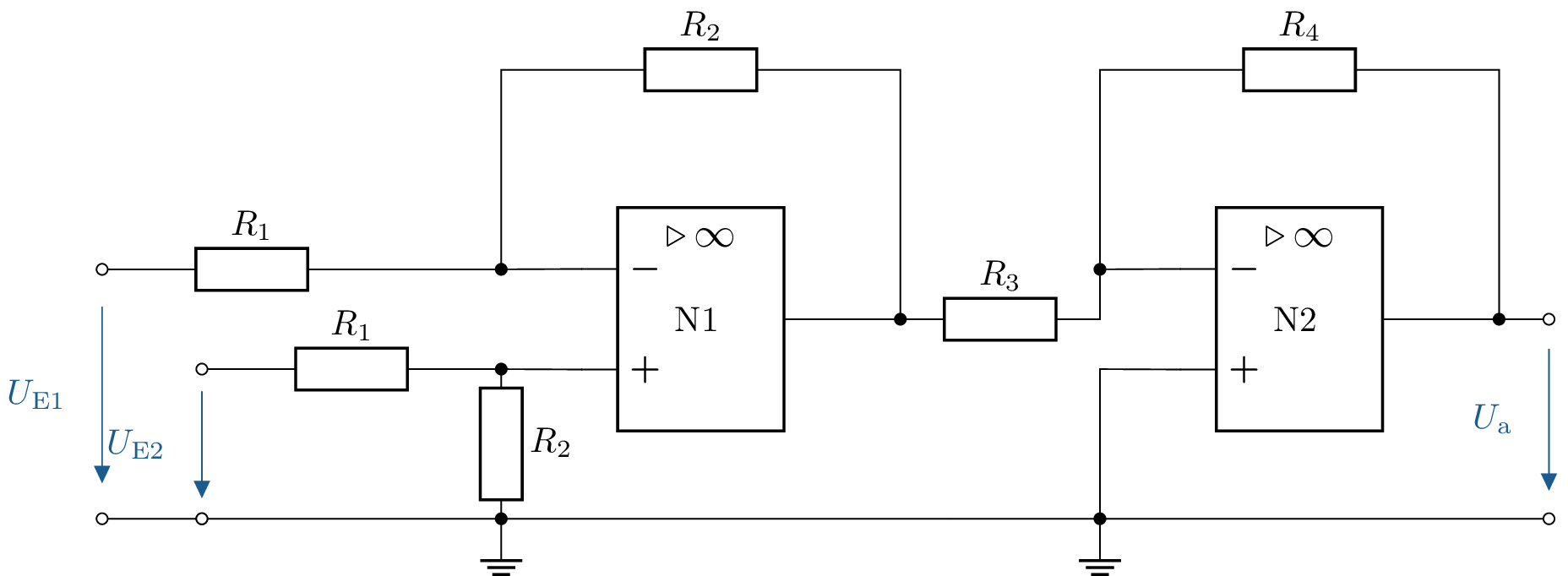
15 Determine the output voltage of a two-stage operational amplifier circuit
Given is the following circuit. Calculate the output voltage \( U_\mathrm {a} \).
The resistance values are:
\( R_\mathrm {1} = \mathrm {10\,k\Omega },\\ R_\mathrm {2} = \mathrm {30\,k\Omega },\\ R_\mathrm {3} = \mathrm {30\,k\Omega },\\ R_\mathrm {4} = \mathrm {10\,k\Omega } \)
15.1 Lösung:
The output voltage after the first operational amplifier (\( U_\mathrm {a1} \)) is calculated as follows: \begin {align*} U_\mathrm {a1} &= (U_\mathrm {E1} - U_\mathrm {E2}) \cdot \frac {R_\mathrm {2}}{R_\mathrm {1}} \\ U_\mathrm {a1} &= \frac {\mathrm {30\,k\Omega }}{\mathrm {10\,k\Omega }} \cdot (U_\mathrm {E1} - U_\mathrm {E2}) \end {align*}
This results in the following for the total output voltage (\( U_\mathrm {a} \)): \begin {align*} U_\mathrm {a} &= - \frac {R_\mathrm {4}}{R_\mathrm {3}} \cdot U_\mathrm {a1} \\ U_\mathrm {a} &= - \frac {\mathrm {10\,k\Omega }}{\mathrm {30\,k\Omega }} \cdot \frac {\mathrm {30\,k\Omega }}{\mathrm {10\,k\Omega }} \cdot (U_\mathrm {E1} - U_\mathrm {E2}) \\ U_\mathrm {a} &= U_\mathrm {E2} - U_\mathrm {E1} \end {align*}
See section: ?? and Table ??
16 Calculation of an OP circuit with three inputs
The circuit shown below is given. Determine the output voltage \( U_\mathrm {A} \).
The resistance values are:
\( R_\mathrm {1} = \mathrm {10\,k\Omega },\\ R_\mathrm {2} = \mathrm {20\,k\Omega },\\ R_\mathrm {3} = \mathrm {30\,k\Omega },\\ R_\mathrm {4} = \mathrm {10\,k\Omega },\\ R_\mathrm {5} = \mathrm {20\,k\Omega },\\ R_\mathrm {6} = \mathrm {40\,k\Omega } \)
16.1 Lösung:
Calculate the output voltage after the first operational amplifier using the following formula (\(U_{a1}\)): \begin {align*} U_\mathrm {A1} = - (U_\mathrm {E1} \cdot \frac {R_4}{R_1} + U_\mathrm {E2} \cdot \frac {R_4}{R_2} + U_\mathrm {E3} \cdot \frac {R_4}{R_3}) \\ U_\mathrm {A1} = - (U_\mathrm {E1} \cdot \frac {10}{10} + U_\mathrm {E2} \cdot \frac {10}{20} + U_\mathrm {E3} \cdot \frac {10}{30}) \\ U_\mathrm {A1} = - (U_\mathrm {E1} + \frac {1}{2} \cdot U_\mathrm {E2} + \frac {1}{3} \cdot U_\mathrm {E3}) \\ \end {align*}
This results in the following for the total output voltage (\(U_\mathrm {A}\)): \begin {align*} U_\mathrm {A} = - \frac {R_6}{R_5} \cdot U_\mathrm {a1} \\ U_\mathrm {A} = - \frac {40}{20} \cdot (- (U_\mathrm {E1} + \frac {1}{2} \cdot U_\mathrm {E2} + \frac {1}{3} \cdot U_\mathrm {E3})) \\ U_\mathrm {A} = 2 \cdot U_\mathrm {E1} + U_\mathrm {E2} + \frac {2}{3} \cdot U_\mathrm {E3} \end {align*}
See section: ?? and Table ??
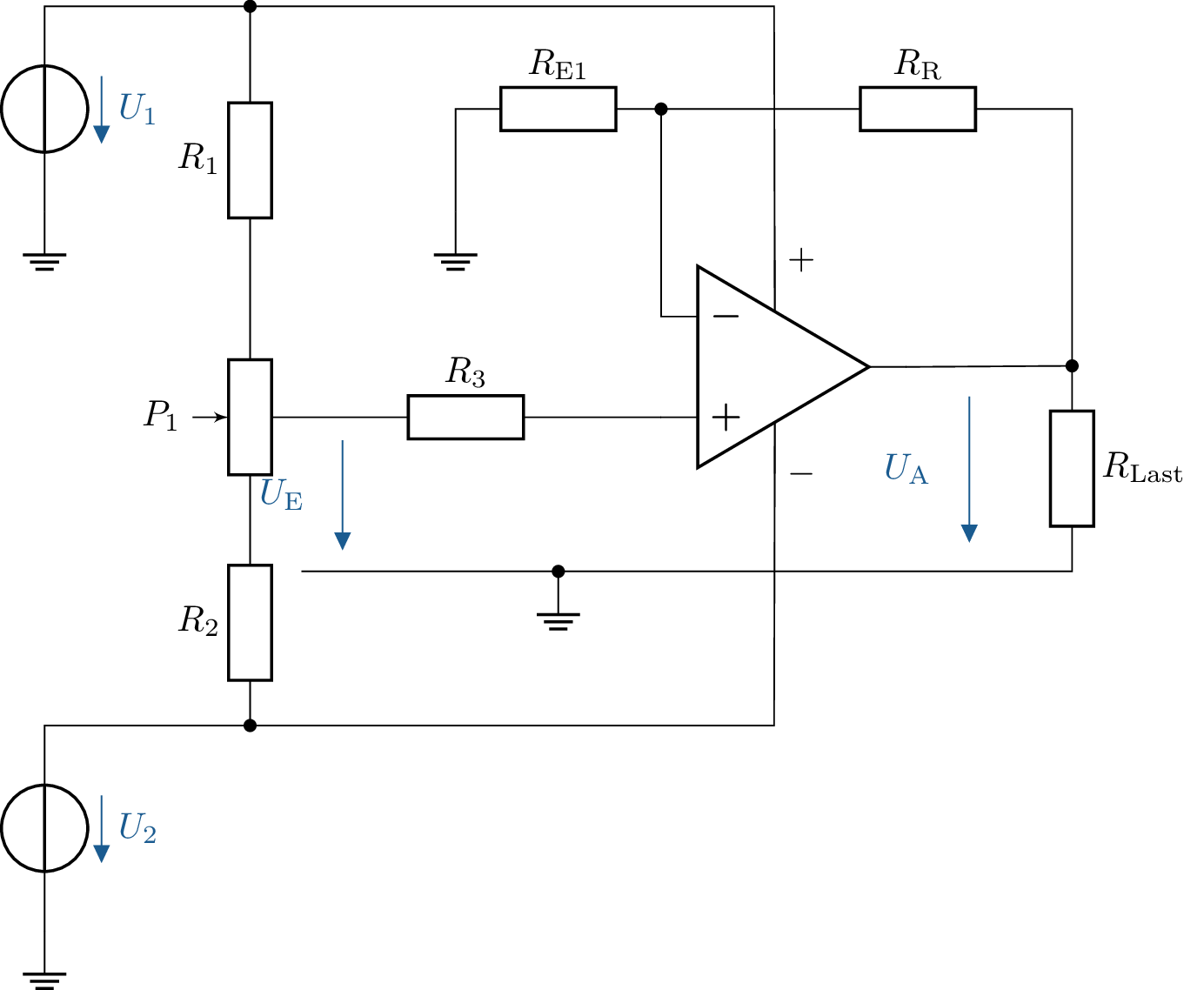
17 Investigation of the amplification of an OP with variable resistors
Investigate the amplification of a non-inverting operational amplifier with variable resistors and calculate the output voltage \(U_\mathrm {A}\). Given:
- Supply voltage: \(\pm 15\,\mathrm {V}\)
- Input voltage: \(U_\mathrm {E} = 1\,\mathrm {V}\)
- Feedback resistance: \(R_\mathrm {R} = 100\,\Omega \)
- Input resistance: \(R_\mathrm {E} = 680\,\Omega \)
- Further possible resistance values: \(R_\mathrm {R} = 220\,\Omega \), \(R_\mathrm {E} = 680\,\Omega \)
- Load resistance: \(R_\mathrm {Last} = 10\,\mathrm {k\Omega }\)
- Calculate the gain \(V\) and the output voltage \(U_\mathrm {A}\) for the given resistor values.
- How does the gain change if \(R_\mathrm {R}\) is increased from \(100\,\Omega \) to \(220\,\Omega \)?
- What effects does a change in \(R_\mathrm {E}\) have on the gain and the output voltage?
- What limitations for \(U_\mathrm {A}\) result from the supply voltage?
17.1 Lösung:
a) Calculation of the output voltage \(U_\mathrm {A}\) for given values
Given is: \[ U_\mathrm {E} = 1\,\mathrm {V}, R_\mathrm {R} = 100\,\Omega , R_\mathrm {E} = 680\,\Omega \] Insert into the amplification formula: \[ V = 1 + \frac {100\,\Omega }{680\,\Omega } = 1 + 0{,}147 = 1{,}147 \] The output voltage is calculated as follows:
\[ U_\mathrm {A} = V \cdot U_\mathrm {E} = 1{,}147 \cdot 1\,\mathrm {V} = 1{,}147\,\mathrm {V} \]
b) Change from \(R_\mathrm {R}\) to \(220\,\Omega \)
When \(R_\mathrm {R} = 220\,\Omega \) is selected: \[ V = 1 + \frac {220\,\Omega }{680\,\Omega } = 1 + 0{,}323 = 1{,}323 \] \[ U_\mathrm {A} = 1{,}323 \cdot 1\,\mathrm {V} = 1{,}323\,\mathrm {V} \]
c) Influence of \(R_\mathrm {E}\) on the gain
An increase in \(R_\mathrm {E}\) leads to a smaller gain \(V\), while a decrease in \(R_\mathrm {E}\) increases the gain. In practice, \(R_\mathrm {E}\) should be
chosen so that the output signal does not fluctuate too much.
d) Limitation of \(U_\mathrm {A}\) by the supply voltage
The output voltage \(U_\mathrm {A}\) can never exceed the supply voltage \(\pm 15\,\mathrm {V}\). If \(U_\mathrm {A}\) would exceed this range according to
calculations, the output voltage is limited to a maximum of \(15\,\mathrm {V}\). See section: ?? and Table ??
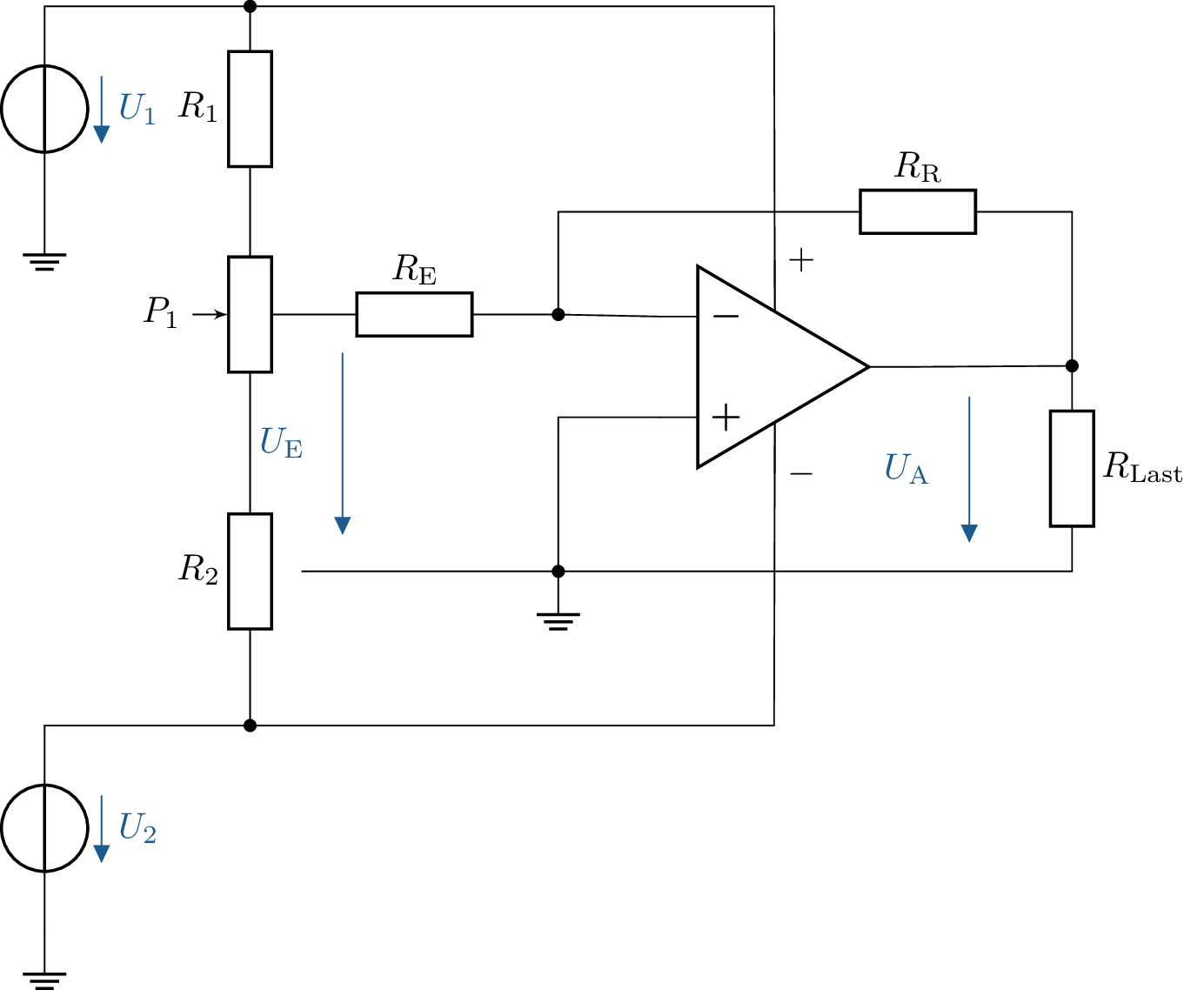
18 Analysis of a non-inverting amplifier with load
Analyse the gain of a non-inverting operational amplifier and calculate the output voltage \(U_\mathrm {A}\). Given:
- Supply voltage: \(\pm 15\,\mathrm {V}\)
- Input voltage: \(U_\mathrm {E} = 1\,\mathrm {V}\)
- Feedback resistance: \(R_\mathrm {R} = 20\,\mathrm {k\Omega }\)
- Input resistance: \(R_\mathrm {E} = 10\,\mathrm {k\Omega }\)
- Load resistance: \(R_\mathrm {Last} = 10\,\mathrm {k\Omega }\)
- Calculate the output voltage \(U_\mathrm {A}\) using the given values.
- How does \(U_\mathrm {A}\) change if \(R_\mathrm {R}\) is increased to \(30\,\mathrm {k\Omega }\)?
- What influence does the load resistor \(R_\mathrm {Last}\) have on the output signal?
18.1 Lösung:
a) Calculation of the output voltage \(\mathrm {U_A}\)
Given are: \[ U_\mathrm {E} = 1\,\mathrm {V}, R_\mathrm {R} = 20\,\mathrm {k\Omega }, R_\mathrm {E} = 10\,\mathrm {k\Omega } \] Insert into the amplification formula: \[ V = 1 + \frac {20\,\mathrm {k\Omega }}{10\,\mathrm {k\Omega }} = 1 + 2 = 3 \] The output voltage is calculated as follows:
\[ U_\mathrm {A} = V \cdot U_\mathrm {E} = 3 \cdot 1\,\mathrm {V} = 3\,\mathrm {V} \]
b) Change from \(\mathrm {R_R}\)
If \(R_\mathrm {R}\) is increased to \(30\,\mathrm {k\Omega }\): \[ V = 1 + \frac {30\,\mathrm {k\Omega }}{10\,\mathrm {k\Omega }} = 1 + 3 = 4 \] \[ U_\mathrm {A} = 4 \cdot 1\,\mathrm {V} = 4\,\mathrm {V} \]
c) Influence of load resistance
The load resistance \(R_\mathrm {Load}\) has only a minimal effect on the circuit as long as the operational amplifier is
operating in the linear range. However, if the load resistance is too small, the operational amplifier may
reach its output current limit, resulting in voltage limitation.
See section: ?? and Table ??
19 Analysis of a loaded voltage divider
Draw a circuit diagram consisting of a loaded voltage divider. The component values are given as follows:
- Resistance: \(R_1 = R_2 = 10\,k\Omega \)
- Load resistance: \(R_\mathrm {L} = 2{,}2\,\mathrm {k\Omega }\)
- Supply voltage: \(U_\mathrm {CC} = +15\,\mathrm {V}\)
- Calculate the output voltage \(U_\mathrm {C}\) without load resistance.
- Calculate the output voltage \(U_\mathrm {C}\) with the connected load resistance. \(\mathrm {R_L}\).
- Explain why the voltage \(U_\mathrm {C}\) drops across the load resistor.
19.1 Lösung:
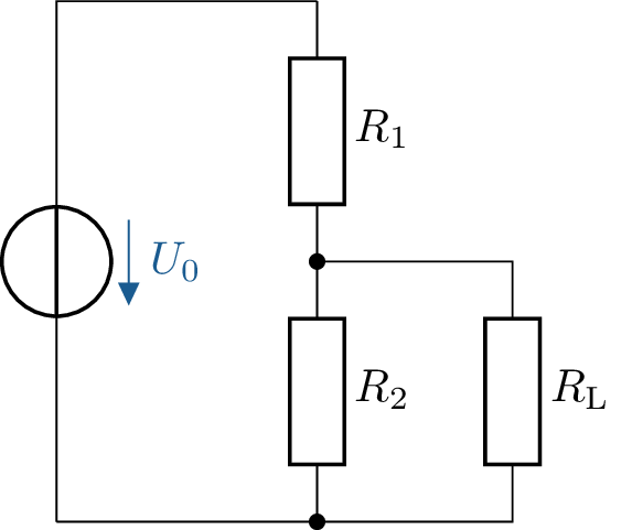
- Calculation of the output voltage \(U_\mathrm {C}\) without load resistance: \begin {align*} U_\mathrm {C} &= \frac {R_2}{R_1 + R_2} \cdot U_\mathrm {CC} \\ U_\mathrm {C} &= \frac {10\,k\Omega }{10\,k\Omega + 10\,\mathrm {k\Omega }} \cdot 15\,\mathrm {V} \\ U_\mathrm {C} &= \frac {1}{2} \cdot 15\,\mathrm {V} \\ U_\mathrm {C} &= 7{,}5\,\mathrm {V} \end {align*}
- Calculation of the output voltage \(\mathrm {U_C}\) with the connected load resistance \(\mathrm {R_L}\): \begin {align*} U_\mathrm {C} &= \frac {R_2}{R_1 + R_2 + R_\mathrm {L}} \cdot U_\mathrm {CC} \\ U_\mathrm {C} &= \frac {10\,\mathrm {k\Omega }}{10\,\mathrm {k\Omega } + 10\,\mathrm {k\Omega } + 2{,}2\,\mathrm {k\Omega }} \cdot 15\,\mathrm {V} \\ U_\mathrm {C} &= \frac {10\,\mathrm {k\Omega }}{22\,\mathrm {k\Omega }} \cdot 15\,\mathrm {V} \\ U_\mathrm {C} &= \frac {10}{22} \cdot 15\,\mathrm {V} \\ U_\mathrm {C} &= \frac {150}{22}\,\mathrm {V} \\ U_\mathrm {C} &\approx 6{,}82\,\mathrm {V} \end {align*}
- The voltage \(U_\mathrm {C}\) decreases due to the load resistor \(R_\mathrm {L}\), as it forms a voltage divider with resistors \(R_1\) and \(R_2\). The load resistor \(R_\mathrm {L}\) draws part of the voltage from the circuit, causing the output voltage \(U_\mathrm {C}\) to drop.
See section: ?? and Table ??
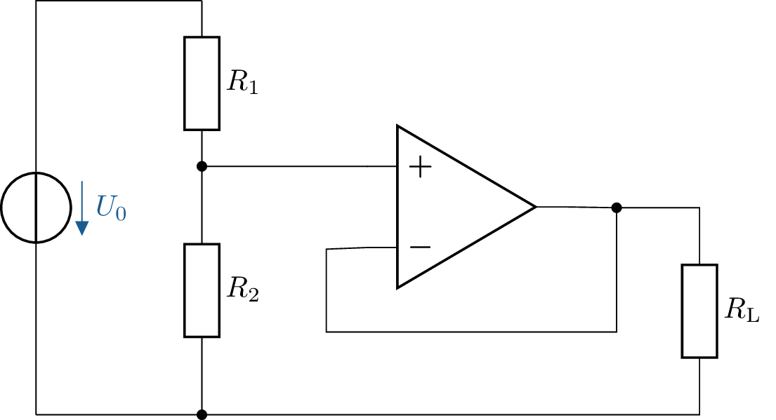
20 Voltage divider with operational amplifier as voltage follower
Draw a new circuit diagram consisting of a loaded voltage divider supplemented by an operational amplifier as an impedance converter. The component values are given as follows:
- Resistances: \(R_1 = R_2 = 10\,\mathrm {k\Omega }\)
- Load resistance: \(R_\mathrm {L} = 2{,}2\,\mathrm {k\Omega }\)
- Supply voltage: \(\mathrm {U_{CC} = +15\,V}\)
The operational amplifier is connected as an impedance converter (voltage follower). Its output feeds the load resistor. \(R_\mathrm {L}\).
- Calculate the output voltage \(U_\mathrm {C}\) with and without the load resistor \(\mathrm {R_L}\).
- Compare the results with those from Exercise 13.
- Explain why the voltage \(U_\mathrm {C}\) does not change due to the load resistor in this circuit.
20.1 Lösung:
- Calculation of the output voltage \(U_\mathrm {C}\) with and without load resistor
Since the operational amplifier is connected as a voltage follower (impedance buffer), the output voltage \(U_\mathrm {A}\) exactly corresponds to the voltage across the voltage divider: \[ U_\mathrm {A} = U_\mathrm {C} = 7{,}5\,\mathrm {V} \] Since the operational amplifier has a very high input resistance, the voltage is not affected by the load resistance. Thus, the output voltage remains constant at 7.5 V, regardless of whether \(R_\mathrm {L}\) is connected or not. - Compare with task 13.
In contrast to the first circuit, the voltage does not drop when the load resistor \(R_\mathrm {L}\) is connected. The operational amplifier decouples the voltage divider from the load, so that the voltage divider always maintains its original voltage. - Explanation of voltage stability through the operational amplifier
As an impedance converter, the operational amplifier has a high input resistance and a low output resistance. As a result, the load resistance is no longer directly connected to the voltage divider, but receives its current from the OPV. This means that the output voltage remains stable, regardless of the load.
See section: ?? and Table ??
21 Investigation of a step-up converter for voltage boosting
An upward converter can be used to convert small DC voltages (e.g. from a battery) into a higher DC voltage. Examine how an upward converter works by analysing the circuit.
Gegeben:
- Input voltage: \(U_\mathrm {E} = 1\,\mathrm {V}\)
- inductance: \(L = 900\,\mathrm {\mu H}\)
- Diode: Ideal diode (no voltage drops taken into account)
- capacitor: \(C = 470\,\mathrm {\mu F}\)
- Switch: Opens and closes periodically
-
Explain how the step-up converter works in two phases:
- Phase 1: Switch closed
- Phase 2: Switch open
- Derive the formula for the output voltage \(U_\mathrm {A}\) as a function of the duty cycle \(D\): \[ U_\mathrm {A} = \frac {U_\mathrm {E}}{1 - D} \]
-
Calculate \(U_\mathrm {A}\) for different duty cycles \(D\):
- \(D = 0{,}3\)
- \(D = 0{,}5\)
- \(D = 0{,}7\)
- What happens when \(D\) approaches \(1\)? What practical limitations are there?

21.1 Lösung:
a) Explanation of how the step-up converter works
The step-up converter operates in two phases:
- Phase 1 (switch closed): The inductance \(L\) is charged with current and stores energy in its magnetic field. The diode blocks the current, so that no current flows to the output.
- Phase 2 (switch open): The stored magnetic flux of the inductance collapses, causing the inductance to induce a voltage. This voltage adds to the input voltage and charges the capacitor \(C\) to a higher voltage. The output now receives a higher voltage than the input voltage.
b) Derivation of the output voltage formula
In a steady state, the ratio between input and output voltage applies: \[ U_\mathrm {A} = \frac {U_\mathrm {E}}{1 - D} \] where \(D\) is the duty cycle (ratio of the
time during which the switch is closed).
c) Calculation of the output voltage for different \(D\)
Given is \(U_\mathrm {E} = 1\,\mathrm {V}\).
- For \(D = 0{,}3\): \[ U_\mathrm {A} = \frac {1\,\mathrm {V}}{1 - 0{,}3} = \frac {1\,\mathrm {V}}{0{,}7} = 1{,}43\,\mathrm {V} \]
- For \(D = 0{,}5\): \[ U_\mathrm {A} = \frac {1\,\mathrm {V}}{1 - 0{,}5} = \frac {1\,\mathrm {V}}{0{,}5} = 2\,\mathrm {V} \]
- For \(D = 0{,}7\): \[ U_\mathrm {A} = \frac {1\,\mathrm {V}}{1 - 0{,}7} = \frac {1\,\mathrm {V}}{0{,}3} = 3{,}33\,\mathrm {V} \]
d) Limits for \(D \to 1\)
Theoretically, \(U_\mathrm {A} \to \infty \) if \(D\) approaches \(1\). In practice, however, there are limitations due to:
- Inductance saturation
- Losses due to resistors, diodes and switches
- Limited switching frequencies
Typical values for \(D\) are usually below 0.8 to ensure stable operation.
