
In Module 7
Fundamentals of Complex Numbers
Pointer diagrams in alternating current technology
Complex alternating current calculation

In alternating current technology, complex numbers are used, among other things, as pointers. In linear networks, sinusoidal and single-frequency source quantities only result in sinusoidal and single-frequency voltages and currents. In a steady state, the voltages and currents only differ in their amplitude and the associated phase. All signals have an identical frequency. Steady-state and harmonic oscillations can be represented by their time course in a line diagram or by complex numbers using pointers. Describing oscillations using complex numbers allows them to be represented by stationary pointers, whereby only their relative position to each other is expressed.
Learning objectives: Pointer diagrams
the students can
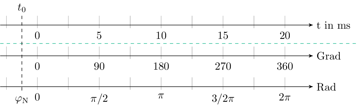
Figure 1 shows an alternating voltage signal with a peak value (amplitude value) of \(\hat {U}\). The offset of the alternating voltage signal on the abscissa is expressed by the time \(t_\mathrm {0}\). The point at which the alternating voltage signal crosses the ordinate indicates the alternating voltage value \(U\) at time \(t=0\).
The alternating voltage signal is periodic in \(T\). A period is defined for the specified alternating voltage signal by a complete cycle of a positive and negative half-wave. Thus, starting from \(t_\mathrm {0}\), after one period, the time \(t_0+T\) is reached, and after two periods, the time \(t_\mathrm {0+2T}\) is reached.
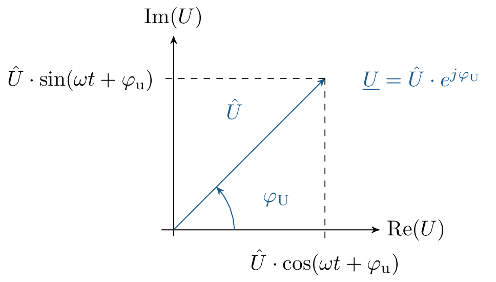
By transferring the specified values to a circular diagram, the relationship between the alternating voltage and the complex representation can be explained. In this way, the alternating voltage magnitude \(U(t=0)\) at time \(0\) can be described by the length and orientation of the pointer. The peak value corresponds to the length of the pointer in the circular diagram. The angle \(\varphi _\mathrm {u}\) describes the phase angle at time \(t=0\).
The angular frequency \(\omega \) can be specified using the period \(T\) or the frequency \(f\). Furthermore, the angular frequency is also described as angular velocity. Using the relationship between the period and the frequency, the quantities can be converted into one another. The relationships explained are described in equations 1.
\begin {equation} \omega = \frac {2\pi }{T} {\text { with } f=\frac {1}{T} } {\text { will be } \omega = 2\pi f \label {GleichungKreisfrequenz}} \end {equation}
Assuming that the cycle of a complete period at a frequency of \(50 Hz\) takes \(20 ms\) (see Figure 2). Applied to the degree measure and the wheel measure, this results in angle specifications for the cycle of a period. The angle after the complete period T corresponds to the rotation of a full circle. The rotation of a full circle corresponds to the phase shift \(t_\mathrm {0}\) can also be described in angular representation as the phase angle \(\varphi _\mathrm {N}\).
Key point: Exchangeable sizes
An alternating voltage explains a regular polarity change with the amplitude value \(\hat {U}\) and the Periodendauer \(T\).
The time-dependent voltage value \(u(t)\) of an alternating voltage depends on several influencing factors. These include the peak value and frequency of the alternating voltage as well as the corresponding phase angle. \(u(t)\) can be determined from the ratio of the time t to the period duration.
\begin {equation} u(t) = \hat {U} \cdot \sin (\omega t + \varphi _\mathrm {N}) = \hat {U} \cdot \sin (2\pi f t + \varphi _\mathrm {N}) = \hat {U} \cdot \sin (2\pi \frac {t}{T} + \varphi _N) \label {GleichungSpannung} \end {equation}
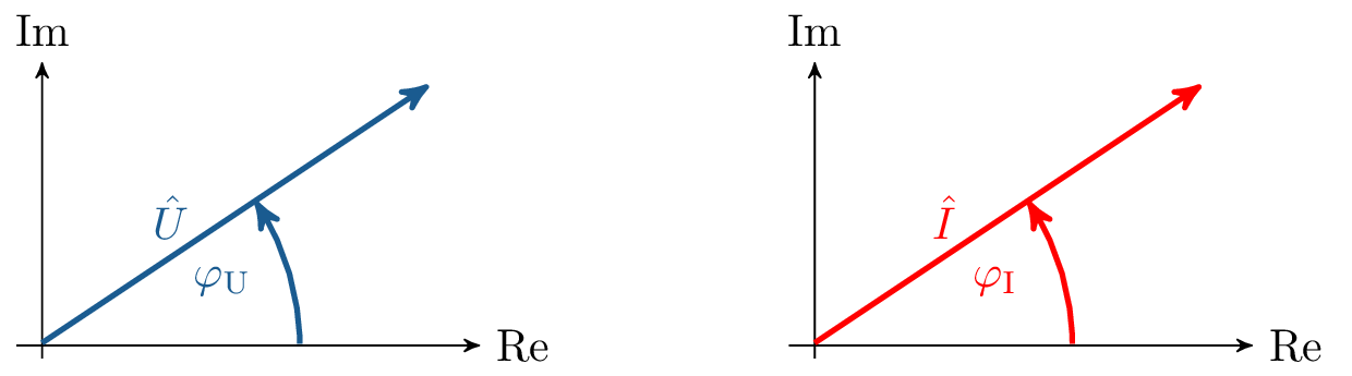
The complex voltage value and the complex current value can be represented as pointers. Here, the polar coordinate representation is used.
A harmonic alternating quantity can be represented as a pointer rotating at a constant angular velocity \(\omega \). The time function is the projection of the pointer onto the real axis. The rotating pointer is described by a time-dependent complex number. As explained for complex numbers, the imaginary part and the real part can be separated. The time function is the projection of the pointer onto the real axis. The rotating pointer is described by a time-dependent complex number. As explained for complex numbers, the imaginary part and the real part can be determined separately. The real part and the imaginary part of the complex voltage can be calculated using trigonometric functions.
Key point: Complex rotating pointers for voltage and current
The alternating variables voltage and current are represented as complex rotating pointers. The rotating pointers describe instantaneous values \(u(t)\), which, with constant angular velocity \(\omega \) change.
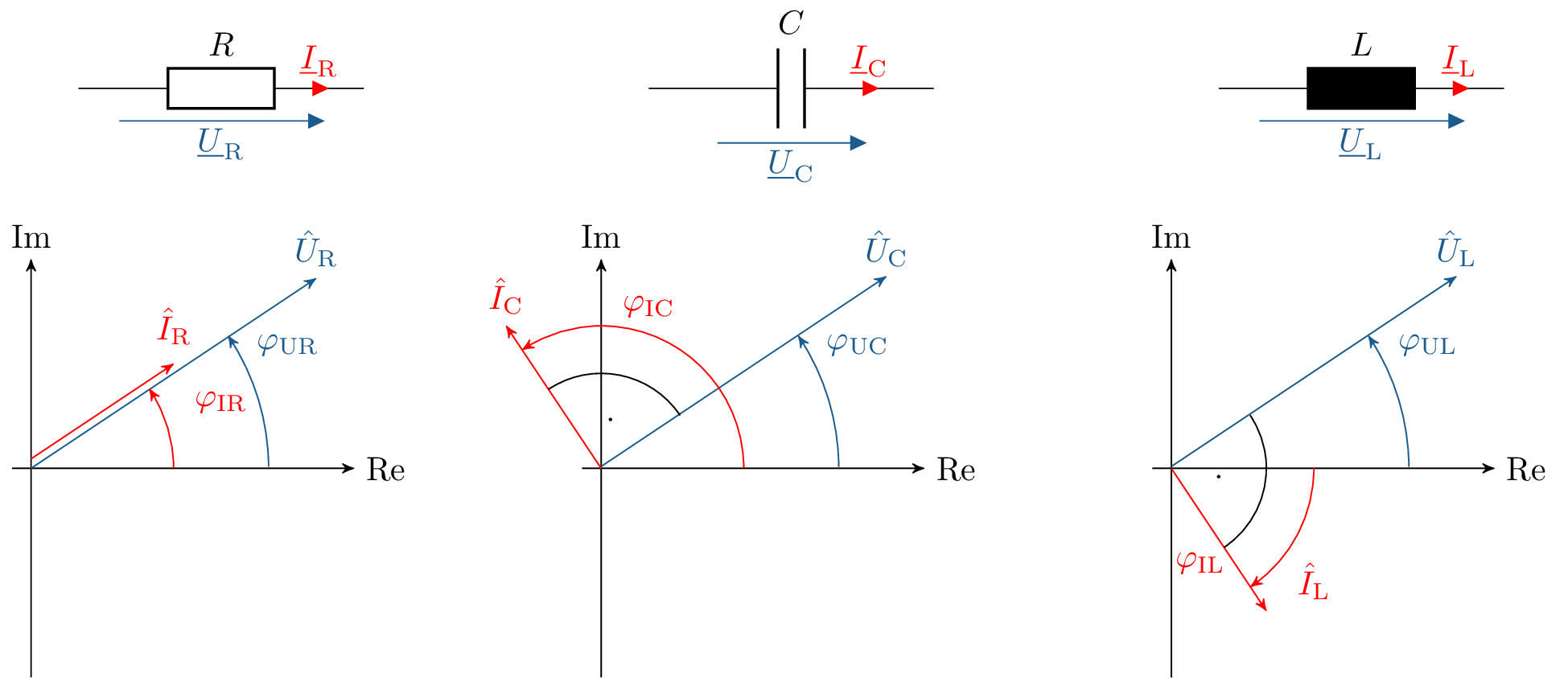
Periodic quantities in electrical components are described by fixed voltage indicators and current indicators. The behaviour of the various components differs in each case. Figure 5 shows a resistor, a capacitor as capacitance and a coil as inductance with their associated voltage and current vectors. The exact behaviour of the three components will be examined in more detail in the following chapter.

Pointer diagrams in alternating current technology
Complex alternating current calculation...