

Inductance and coil
The counterpart to the capacitor is the coil, or more precisely: the counterpart to capacitance \(C\) is inductance \(L\). Inductance is also an energy storage device, but the difference lies in the type of fields used. While capacitance stores energy in the form of an electric field, inductance does so via the magnetic field.
Learning objectives: Inductance and coil
The Students
- can differentiate between inductance and coils.
- know the most important parameters relating to inductance and coils.
- can calculate the inductance of a coil.
1 The inductance \(L\)
Inductance is the ability of an object to store electrical energy in the form of a magnetic field. This property occurs when an electric current flows through a conductor, around which a magnetic field forms. The symbol for inductance is \(L\) (named after the French physicist Heinrich Lenz), while the unit is given in henries (\(\mathrm {H}\)).
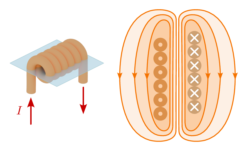
The simplest and most common example used to explain inductance is the coil. Although the phenomenon of inductance already occurs in a simple conductor, this effect is deliberately amplified by the construction of a coil. Figure 1 shows a cylindrical air coil with its magnetic flux density \(\vec {B}\).
The topic of magnetic quantities is covered in detail in Module 6. To understand how a coil works and the resulting inductance, a brief introduction to the origin of magnetism will help.
As soon as current flows through a straight conductor, a magnetic field is created concentrically around the conductor. The magnetic field also changes depending on the current strength and direction. The right-hand rule serves as a mnemonic device for determining the direction and orientation of the magnetic field.
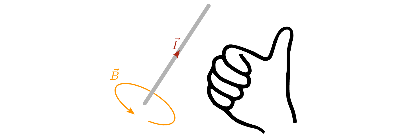
According to the diagram 2, the magnetic field runs concentrically around the conductor in the direction of the fingertips, provided that the thumb is aligned in the direction of the technical current flow, i.e. opposite to the direction of electron flow. The magnetic field rotates from south to north and has a flux density \(\vec {B}\) and a field strength \(\vec {H}\). It should be noted that the magnetic flux density \(\vec {B}\) behaves analogously to the electric field strength \(\vec {E}\), and the magnetic field strength \(\vec {H}\) behaves analogously to the electric flux density \(\vec {D}\). Module 6 deals with the topic of magnetism in more detail. This module is primarily about getting to know the coil and inductance.
In the mid-19th century, British physicist and chemist Michael Faraday conducted experiments in which he moved a coil near a magnet or changed the current in an adjacent coil. He found that the magnitude of the induced voltage was proportional to the rate of change of the magnetic field.
\begin {equation} U_\mathrm {i} \sim \frac {\mathrm {d}\phi }{\mathrm {d}t} \end {equation}
Faraday discovered that the proportionality factor depends on the number of windings in the coil.
\begin {equation} U_\mathrm {i}= -N \cdot \frac {\mathrm {d}\phi }{\mathrm {d}t} \end {equation}
At around the same time, American physicist Joseph Henry discovered the phenomenon of self-induction, whereby an electric current in a coil can induce a voltage in the coil itself when the current is changed. Here, too, proportional behaviour was observed.
\begin {equation} U_\mathrm {i} \sim \frac {\mathrm {d}I}{\mathrm {d}t} \end {equation}
This property of the coil, which arises from the storage of magnetic energy, is the inductance \(L\), whose unit was named Henry \([\mathrm {H}]\) in honour of the physicist.
\begin {equation} U_\mathrm {i}= -L \cdot \frac {\mathrm {d}I}{\mathrm {d}t} \end {equation}
The minus sign comes from the fact that, according to Lenz’s law, the induced current counteracts its cause.
Analogous to the capacitor, the time-dependent behaviour for the coil can also be expressed as follows:
Voltage across the inductance \begin {equation} u_\mathrm {L}(t) = L \cdot \frac {di_\mathrm {L}(t)}{dt} \end {equation} Current through the inductance \begin {equation} i_\mathrm {L}(t) = \frac {1}{L} \cdot \int u_\mathrm {L}(t) \, dt \end {equation}
2 The coil as a component
With knowledge of the magnetic field, the structure and function of the coil can now be explained. A simple example of this is the cylindrical air coil. When a conductor is formed into a conductor loop, the magnetic field is formed in such a way that it passes through the loop opening. If several conductor loops are wound one behind the other, the magnetic field is amplified by the number of turns. This arrangement of wound conductor loops results in the cylindrical air coil shown in Figure 3.
This coil owes its name to its cylindrical shape in the longitudinal direction and the medium of air inside its
windings. When a current flows through the coil, the magnetic fields of the individual windings superimpose
to form a stronger magnetic field. The strength depends on the number of turns and the current, as
well as the distance to the conductor. Depending on the orientation of the current and the
windings, a cylinder air coil produces a north pole on one side and a south pole on the other.
The course of the magnetic field lines in a cylindrical air coil corresponds to the illustration 1.
What all coils have in common is their ability to utilise the property of inductance, as shown in the following circuit diagram 5. However, this circuit diagram only represents the idealised, usable inductance.
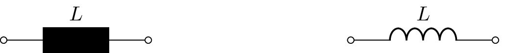

For a realistic simulation of the circuit, it is important to describe the coil as a component in its entirety. This is done with the help of an equivalent circuit diagram, which also simulates the unwanted, i.e. parasitic, properties of the component. Figure 6 shows such an equivalent circuit diagram.

The equivalent circuit diagram of a coil takes into account not only the usable inductance, but also the parasitic properties that occur in real coils. These parasitic properties arise, for example, from the capacitances between the windings and the ohmic losses in the material. The modelled equivalent circuit diagram makes it possible to take these effects into account in the circuit design and to better predict the switching behaviour.
Key point:
The coil is a desperate attempt to replicate inductance.
3 Permeability
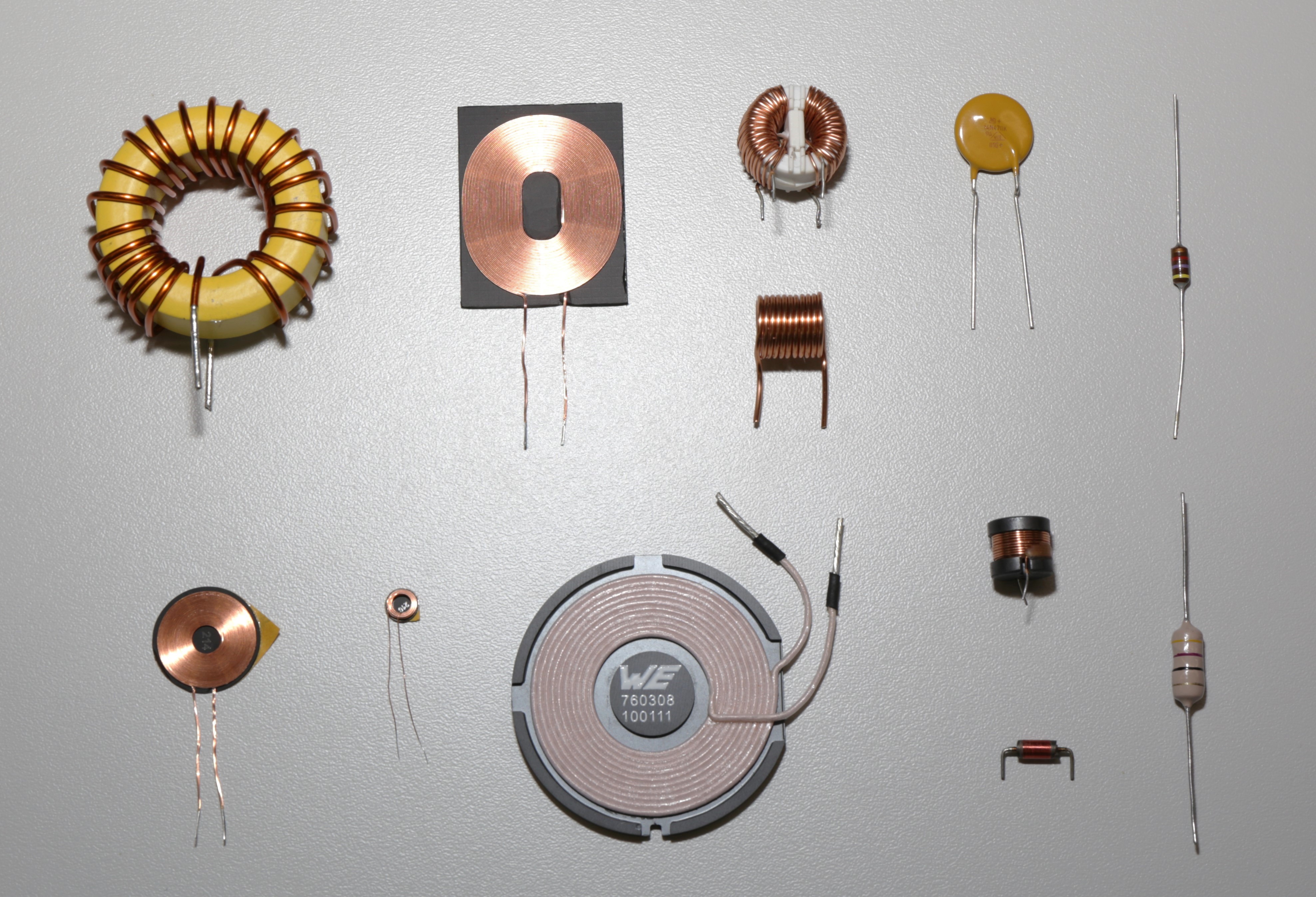
Similar to the case of the capacitor and capacitance, the strength of the magnetic field also varies depending on the material. What are the dielectric and permittivity in the case of the capacitor are referred to as ferromagnetic material and permeability in the case of the coil. An example of a coil with a ferromagnetic material is the toroidal coil 7..

The toroidal coil is a ferrite ring wrapped with wire. Alignment takes place at the atomic level within the material, which leads to a strengthening of the magnetic field. The strength of the magnetic flux density \(\vec {B}\) is determined not only by the dimensions and current strength, but also by the material properties, in particular the permeability.
The following table 1 shows the permeability coefficient of some common materials:
| Material | \(\mu _\mathrm {r}\) |
| Type I superconductor | \(0\) |
| Vacuum | £1 |
| Air (at STP) | £1.00000037 |
| Copper | £0.999994 |
| Gold | £0.999964 |
| Aluminium | £1.000022 |
| Iron | \(300-10000\) |
| Ferrite | \(4-15000\) |
In order to fully describe the properties of ferromagnetic material, in addition to the permeability coefficient, the magnetic field constant \(\mu _0\) is also required. This refers to the behaviour of the magnetic field in a vacuum. While the permeability coefficient \(\mu _r\) is dimensionless, the magnetic field constant has the unit \(\mathrm {H/m}\). It is multiplied by the relative permeability of the material, which together gives the permeability constant \(\mu \)..
\begin {equation*} [\mu ] = 1\, \frac {\text {Henry}}{\text {m}} = 1\, \frac {\text {H}}{\text {m}} = 1\, \frac {\text {Vs}}{\text {Am}} \end {equation*} \begin {equation} \mu = \mu _\mathrm {r} \cdot \mu _\mathrm {0} \end {equation}
\begin {align*} \mu &: \text {Permeability constant}\\ \mu _\mathrm {0} &: \text {Magnetic field constant ($\approx 4\pi \cdot 10^{-7}$)}\\ \mu _\mathrm {r} &: \text {Relative permeability coefficient} \\ \end {align*}
With the help of the permeability, the current, the number of turns and the length of the coil, the magnetic flux density \(\vec {B}\) can be calculated using the unit Tesla \(\mathrm {T}\).
\begin {equation} \vec {B} = \mu \cdot \vec {H} \end {equation}
\begin {align*} [B] = \frac {\text {H/m} \cdot \text {A} \cdot 1}{\text {m}} = \frac {\text {H} \cdot \text {A}}{\text {m}^2} = \frac {(\text {V} \cdot \text {s / } \cancel {\text {A}}) \cdot \cancel {\text {A}}}{\text {m}^2} = \frac {\text {V} \cdot \text {s}}{\text {m}^2} = \text {T (Tesla)} \end {align*}
\begin {equation} B = \frac {\mu \cdot I \cdot N} {l} \end {equation}
\begin {align*} \mu &: \text {Permeability constant} \\ I &: \text {Electrical currente} \\ N &: \text {Number of turns} \\ l &: \text {Length of the magnetic circuit} \end {align*}
The inductance itself also depends on the design and the materials used. \begin {equation*} [L] = 1\, \text {Henry} = 1\, \text {H} = 1\, \frac {\text {Vs}} {\text {A}} \end {equation*} \begin {equation} L = \frac {\mu \cdot N^2 \cdot A}{l} \end {equation}
4 The magnetic field strength
\begin {equation} \vec {B} = \mu \cdot \vec {H} \end {equation}
5 Switching behaviour of a coil
To better understand how a coil works, let us now consider a time-varying signal, in this case the switch-on and switch-off process. The basic principle of inductance is based on the fact that a time-varying current generates a time-varying magnetic field. This time-varying magnetic field in turn induces an induction current in the coil itself. However, due to Lenz’s law, the induction current acts against its cause, which prevents a sudden increase in current.
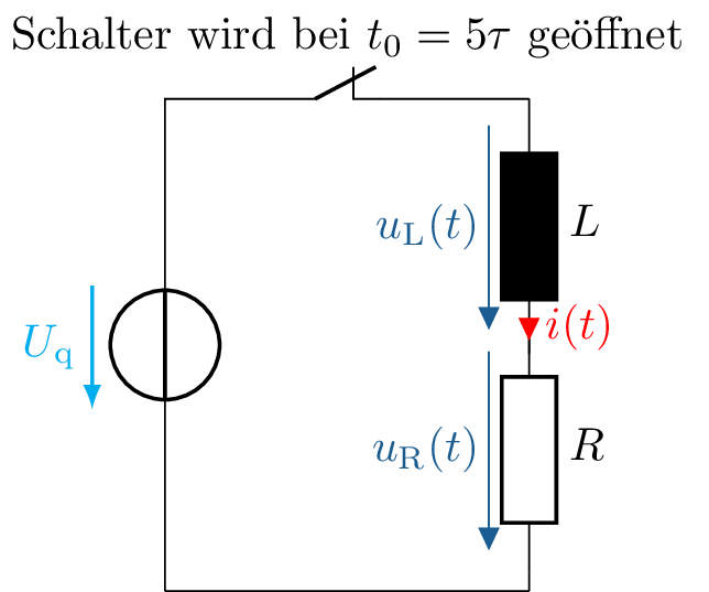
(a) Representation of the series connection consisting of an inductance \(L\), a resistor \(R\) and a switch.

(b) Voltage and current waveform across the inductance for a DC voltage that is switched on at
time \(t = 0\) and switched off at time \(t_\mathrm {0}\).
Figure 8: The voltage and current curve across the inductance. The diagram shows the
reaction of the inductance to the sudden change in voltage and illustrates the typical charging
behaviour.
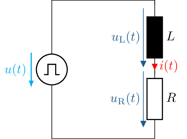
(a) Representation of the series connection consisting of an inductance \(L\) and a resistor \(R\)
connected to a rectangular voltage source.
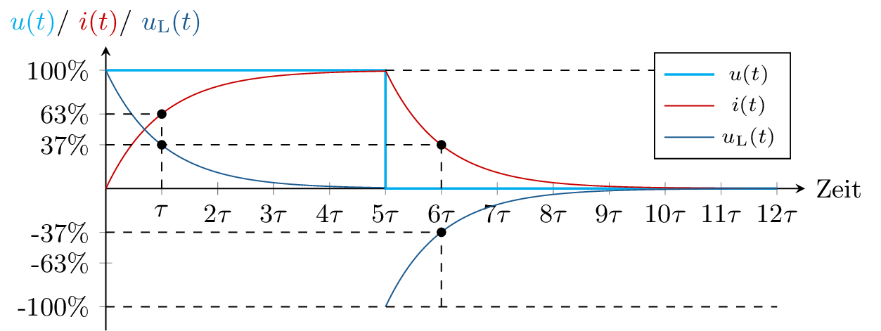
Figure 9: Voltage and current curve across the inductance. The diagram shows the reaction
of the inductance to a sudden change in voltage and illustrates the typical charging and discharging
behaviour of the inductance.
In practical applications, inductance enables the construction of components such as transformers, chokes and inductors, which are found in a wide range of electrical and electronic devices. From signal filtering and energy transmission to the control of electromagnetic interference, inductance is a key element in modern electrical engineering.
Calculation of inductance
- Calculation of inductance \(L\)
- Calculation of magnetic flux density \(\vec {B}\)
- Energy stored in the magnetic field \(E_\mathrm {m}\) ?
