

Inductance
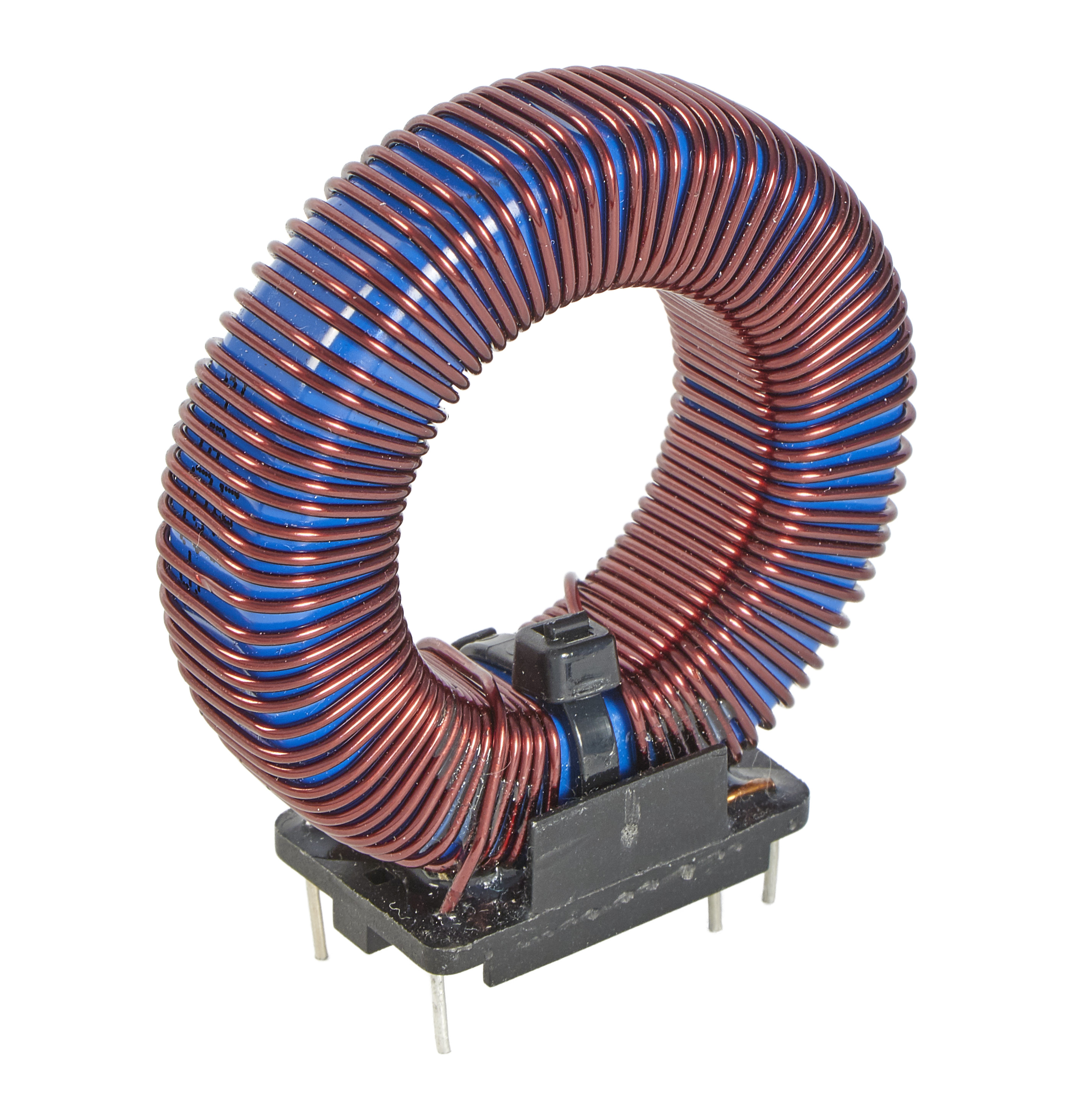
Inductance describes the ability to store electrical energy in a magnetic field. Components that have this ability are called coils (Figure 1), chokes or inductors.

The functioning of an inductor is based on the electromagnetic field generated by the flow of current. This electromagnetic field induces a current in adjacent conductor coils of the component. This effect allows electrical energy to be temporarily stored in a magnetic field. For a better understanding, the function of inductance is explained step by step below. A current flows through a conductor loop. This current generates a magnetic field whose strength is proportional to the current strength – the stronger the current, the stronger the magnetic field. If the current strength is continuously changed, this also causes a change in the magnetic field, which in turn (as described in chapter ??) induces a voltage in neighbouring conductor loops. This induced voltage counteracts the change in current according to Lenz’s law. Consequently, when the current source is switched on at the coil, the induced voltage counteracts the current flow, so that the current only increases gradually. When the coil is switched off, the induced voltage causes the current to continue to flow for a while. This phenomenon, also known as self-induction, enables magnetic storage. The inductance therefore indicates how strongly an electrical component self-induces. The level of inductance \(L\) depends on the number of turns \(N\), the permeability of the coil core \(\mu _r\), the cross-sectional area of the core and the geometric shape of the component. For inductors, the magnetic field is generally proportional to the value of the current.
The inductance \(L\) can be calculated in two different ways using the unit Henry (H). On the one hand, it can be calculated using the relationship between the resulting magnetic field \(N \cdot \varPhi \) and the causing current \(I\) (as in equation 1).
\begin {equation} L = \frac {N \cdot \varPhi }{I} \label {InduktivitaetFormel} \qquad [\mathrm {H}] \end {equation}
On the other hand, for simple geometric structures such as cylindrical, rectangular or toroidal coils, the inductance can be determined from the relationship between the number of turns \(N^2\) and the magnetic resistance \( R_{\mathrm {m}} \) (Equation 2).
\begin {equation} L=\frac {N^2}{R_{\mathrm {m}}} \label {InduktivitaetFormel2} \qquad [\mathrm {H}] \end {equation}
Key point: Inductance
Inductance \(L\) describes a component that is capable of storing electrical energy in a magnetic field.
The calculation of the voltage of an inductor can be derived from the calculation of the voltage of an induction (equation ??).
\begin {equation} u_{\mathrm {i}} = -N\cdot \frac {\mathrm {d}\varPhi }{\mathrm {d}t} \tag {\ref {GlInduktionsgesetz}} \end {equation}
The voltage of an inductance \(u\) is a change in current \({\mathrm {d}i}/{\mathrm {d}t}\) over time multiplied by the inductance \(L\). Lenz’s law also applies here, resulting in a negative sign.
\begin {equation} u =-L\cdot \frac {\mathrm {d}i}{\mathrm {d}t}\label {GLInduktivitaet2} \end {equation}
In circuit diagrams, inductors are represented by black filled rectangles, as shown in the upper of the two figures 3. Less commonly, a coiled conductor is used to represent an inductor, as shown in the lower figure 3.

There are two ways to determine the inductance of a structure: by measuring the field strengths or by measuring the magnetic resistance.
Method 1 using field sizes:
- 1.
- Assumption of a
current \(I\) \(\rightarrow \) flux\(\Theta = N\cdot I\)
- 2.
- Calculate field strength
\(H=\frac {\Theta }{\ell _{\mathrm {m}}}\)
- 3.
- Calculate flux density
\(B=\mu _{\mathrm {r}}\cdot \mu _0\cdot H\)
- 4.
- Determine magnetic flux
\(\varPhi = \iint _A \vec {B}\cdot \mathrm {d}\vec {A}\)
- 5.
- Inductance
\(L=\frac {N\cdot \varPhi }{I}\)
Method 2 via magnetic
resistance:
resistance:
- 1.
- Divide the magnetic circuit
into sections and magnetic
resistance \(R_{\mathrm {m}}\) calculate\(R_{\mathrm {m}}=\frac {\ell _{\mathrm {m}}}{\mu _{\mathrm {r}}\cdot \mu _0\cdot A}\)
- 2.
- Calculate total resistance
(for series structure)\(R_{m,\mathrm {ges}} = \sum R_{\mathrm {m}}\)
- 3.
- Inductance
\(L=\frac {N^2}{R_{m,\mathrm {ges}}}\)
Inductance In a toroidal coil with an air gap, the influence of the air gap \(d\) on the inductance \(L\) is to be investigated. The coil has \(N=100\) turns. The relative permeability is \(\mu _{\mathrm {r}}=2000\). The average iron core length is \(\ell _{\mathrm {m}}=5\,\mathrm {cm}\). The cross-sectional area is \(A=1\,\mathrm {cm}^2\).
-
The air gap does not exist for the time being: \(d=0\). How large is the inductance \(L\)?
\begin {align*} R_{\mathrm {m}} & = \frac {\ell _{\mathrm {m}}}{\mu _{\mathrm {r}}\cdot \mu _0\cdot A} \\ L & = \frac {N^2}{R_{m}} \\ & = \frac {100^2\cdot 2000\cdot 1,256\cdot 10^{-6}\,\frac {\mathrm {Vs}}{\mathrm {Am}}\cdot 1\cdot 10^{-4}\,\mathrm {m}^2}{0,05\,\mathrm {m}} \\ L & = 0,05\,\frac {\mathrm {Vs}}{\mathrm {A}} = 50\,\mathrm {mH} \end {align*}
- The air gap is now \(d=1\,\mathrm {mm}\). How large is the inductance? \begin {align*} R_{\mathrm {m}} & = R_{m,\mathrm {Fe}} + R_{m,\mathrm {L}} \\ L & = \frac {\ell _{\mathrm {m}} - d}{\mu _{\mathrm {r}}\cdot \mu _0\cdot A} + \frac {d}{\mu _0\cdot A} \\ L & = \frac {0,05\,\mathrm {m} - 0,001\,\mathrm {m}}{2000\cdot 1,256\cdot 10^{-6}\,\frac {\mathrm {Vs}}{\mathrm {Am}}\cdot 1\cdot 10^{-4}\,\mathrm {m}^2} + \frac {0,001\,\mathrm {m}}{ 1,256\cdot 10^{-6}\,\frac {\mathrm {Vs}}{\mathrm {Am}} \cdot 1\cdot 10^{-4}\,\mathrm {m}^2} \\ L & = 1,226\,\mathrm {mH} \end {align*}
