Im Modul 4
Messen von Strom und Spannung
Aufgaben


Berechnen Sie für die Schaltungen die Ströme, Spannungen und Leistungen an den Widerständen. Zeichnen
Sie zu Ihren Ergebnissen alle Strom- und Spannungspfeile ein. Folgende Werte sind gegeben:
\(U_0 = 12 \ V; I_0 = 3 \ A; R_1 = 2 \ \Omega ; R_2 = 4 \ \Omega ; R_3 = 3 \ \Omega ; R_4 = 3 \ \Omega \)
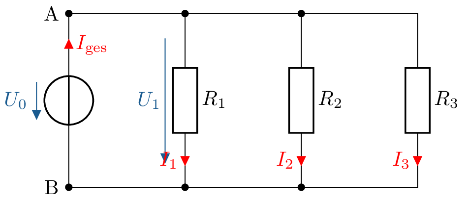
a)
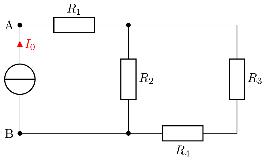
b)
\(I_1 = \frac {U_0}{R_1} = \frac {12 \, \mathrm {V}}{2 \, \Omega } = 6 \, \mathrm {A}\)
\(I_2 = \frac {U_0}{R_2} = \frac {12 \, \mathrm {V}}{4 \, \Omega } = 3 \, \mathrm {A}\)
\(I_1 = \frac {U_0}{R_3} = \frac {12 \, \mathrm {V}}{3 \, \Omega } = 4 \, \mathrm {A}\)
\(I_0 = I_1 + I_2 + I_3 = 13 \, \mathrm {A}\)
Leistung bei Gleichspannung:
\(P = U \cdot I = \frac {U^2}{R} = I^2 \cdot R\)
\(P_1 = U_1 \cdot I_1 = 72 \, \mathrm {W} \)
\(P_2 = U_2 \cdot I_2 = 36 \, \mathrm {W} \)
\(P_3 = U_3 \cdot I_3 = 48 \, \mathrm {W} \)
\(P_\mathrm {ges} = P_1 + P_2 + P_3 = 156 \, \mathrm {W}\)
\(I_1 = I_0 = 3 \, \mathrm {A}\)
\(\rightarrow U_1 = R_1 \cdot I_1 = 2 \Omega \cdot 3 \, \mathrm {A} = 6 \, \mathrm {V}\)
\(I_2\)? Stromteilerregel:
\(I_2 = I_1 \cdot \frac {R_3 + R_4}{R_2 + R_3 + R_4} = 3 \, \mathrm {A} \cdot \frac {6 \, \Omega }{10 \, \Omega } = 1,8 \, \mathrm {A}\)
\(\rightarrow U_2 = R_2 \cdot I_2 = 4 \, \Omega \cdot 1,8 \, \mathrm {A} = 7,2 \, \mathrm {V}\)
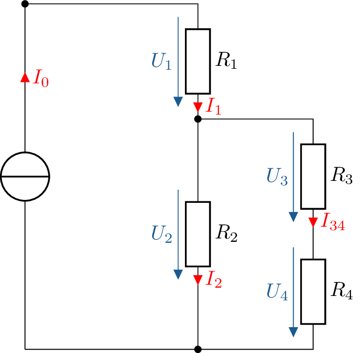
Berechnung von \(U_4?\) Hier Spannungsteiler, theoretisch auch über Knotenregel möglich.
Über die Reihenschaltung \(R_3 + R_4\) liegt eine Gesamtspannung an, die genausogroß wie die dazu
parallelgeschaltete Spannung \(U_2\) ist.
\(U_4 = U_2 \cdot \frac {R_4}{R_3 + R_4} = 7,2 \, \mathrm {V} \cdot \frac {3 \, \Omega }{6 \, \Omega } = 3,6 \, \mathrm {V}\)
\(I_{34} = \frac {U_4}{R_4} = \frac {3,6 \, \mathrm {V}}{3 \, \Omega } = 1,2 \, \mathrm {A}\)
\(U_3 = R_3 \cdot I_{34} = 1,2 \, \mathrm {A} \cdot 3 \Omega = 3,6 \, \mathrm {V}\)
Berechnung der Leistungen:
\(P_1 = U_1 \cdot I_1 = 18 \, \mathrm {W} \)
\(P_2 = U_2 \cdot I_2 = 12,96 \, \mathrm {W} \)
\(P_3 = U_3 \cdot I_{34} = 4,32 \, \mathrm {W} \)
\(P_4 = U_4 \cdot I_{34} = 4,32 \, \mathrm {W} \)
\(P_\mathrm {ges} = P_1 + P_2 + P_3 + P_4 = 39,6 \, \mathrm {W}\)
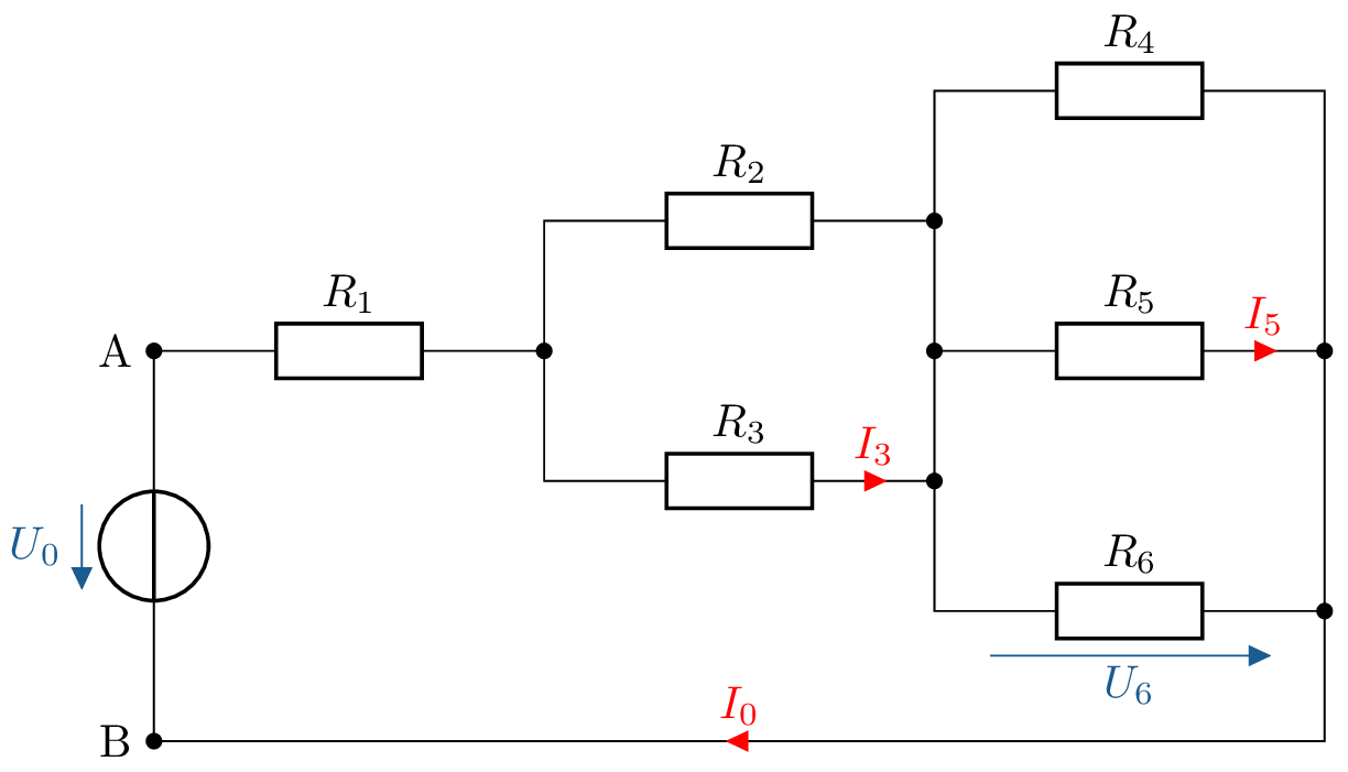
Berechnen Sie für die Schaltung den Gesamtwiderstand \(R_{\mathrm {ges}}\) zwischen den Punkten A und B, die Ströme \(I_0\), \(I_3\), \(I_5\) und
die Spannung \(U_6\). Folgende Werte sind gegeben:
\(R_1 = 5 \ \Omega ; R_2 = 10 \ \Omega ; R_3 = 15 \ \Omega ; R_4 = 20 \ \Omega ; R_5 = 25 \ \Omega ; R_6 = 40 \ \Omega ; U_0 = 80 \ V\).
Parallelgeschaltete Widerstände zusammenfassen:
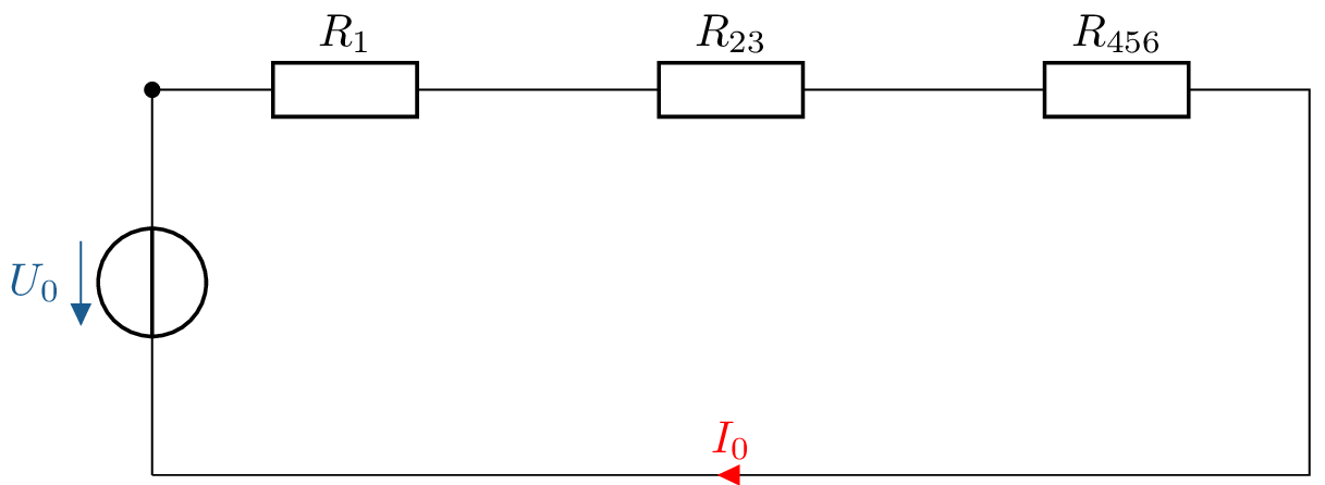
Widerstände berechnen:
\(R_1 = 5 \, \Omega \)
\(R_{23} = \frac {R_2 \cdot R_3}{R_2+R_3} = \frac {10 \, \Omega \cdot 15 \, \Omega }{10 \, \Omega + 15 \, \Omega } = 6 \, \Omega \)
\(R_{456}\) über Kehrwert ausrechnen, im zweiten Schritt Hauptnenner bilden:
\(\frac {1}{R_{456}} = \frac {1}{R_4} + \frac {1}{R_5}+ \frac {1}{R_6} = \frac {R_4 \cdot R_5 + R_4 \cdot R_6 + R_5 \cdot R_6}{R_4 \cdot R_5 \cdot R_6}\)
\(\rightarrow R_{456} = \frac {R_4 \cdot R_5 \cdot R_6}{R_4 \cdot R_5 + R_4 \cdot R_6 + R_5 \cdot R_6} \)
\(R_\mathrm {ges} = R_1 + R_{23} + R_{456} = 19,7 \, \Omega \)
Gesamtstrom berechnen:
\(I_0 = \frac {U_0}{R_\mathrm {ges}} = \frac {80 \, \mathrm {V}}{19,7 \, \Omega } = 4,1 \, \mathrm {A}\)
Teilstrom \(I_3\) mittels Stromteiler berechnen:
\(I_3 = I_0 \cdot \frac {R_2}{R_2 + R_3} = 4,1 \, \mathrm {A} \cdot \frac {10 \, \Omega }{10 \, \Omega + 15 \, \Omega } = 1,6 \, \mathrm {A}\)
\(U_6\) mit Hilfe eines Spannungsteilers berechnen:
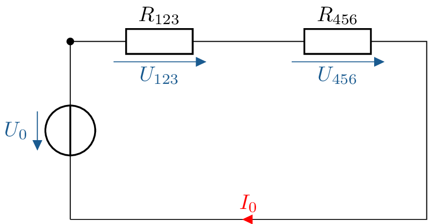
\(R_{123} = R_1 + R_{23} = 11 \Omega \)
Da die drei Widerstände parallel geschaltet sind, ist \(U_6 = U_{456}\)
\(U_6 = U_0 \cdot \frac {R_{456}}{R_{123} + R_{456}} = 80 \, \mathrm {V} \cdot \frac {8,7 \, \Omega }{11 \, \Omega + 8,7 \, \Omega } = 35,3 \, \mathrm {V}\)
\(I_5 = \frac {U_5}{R_5} = \frac {U_6}{R_5} = 1,4 \, \mathrm {A}\)
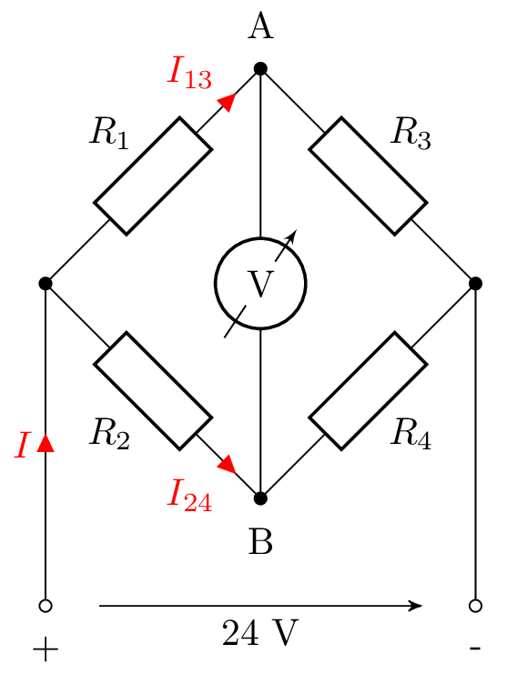
Für die Brückenschaltung sind folgende Werte gegeben: \(R_1 = 4\ \mathrm {k}\Omega , R_2=20 \ \mathrm {k}\Omega , R_3 = 6 \ \mathrm {k}\Omega , R_4 = 20 \ \mathrm {k}\Omega \).
Der Innenwiderstand des Voltmeters kann als unendlich groß angenommen werden. Berechnen Sie die
folgenden Größen:
Für die Brückenschaltung sind folgende Werte gegeben: \(R_1 = 4\ \mathrm {k}\Omega , R_2=20 \ \mathrm {k}\Omega , R_3 = 6 \ \mathrm {k}\Omega , R_4 = 20 \ \mathrm {k}\Omega \).
Der Innenwiderstand des Voltmeters kann als unendlich groß angenommen werden. Berechnen Sie die folgenden Größen:
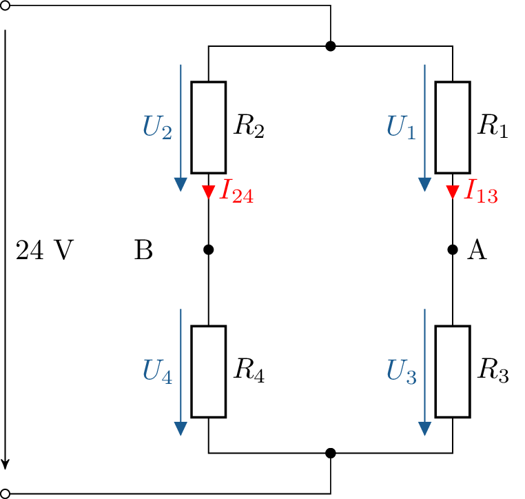
Geringfügiges Umzeichnen erhöht die Übersicht:
Zwei Möglichkeiten, um Teilströme zu ermitteln: Stromteiler oder Ohm´sches Gesetz.
1. Möglichkeit: Stromteiler
Gesamtstrom \(I_0\) ermitteln:
\(I_0 = \frac {U_0}{R_\mathrm {ges}}\)
\(R_\mathrm {ges}= (R_1 + R_3)||(R_2+R_4) = \frac {(R_1+R_3) \cdot (R_2+R_4)}{R_1 + R_2 + R_3 + R_4} = \frac {10 \, \mathrm {k} \Omega \cdot 40 \, \mathrm {k} \Omega }{50 \, \mathrm {k} \Omega } = 8 \, \mathrm {k} \Omega \)
\(I_\mathrm {0} = \frac {24 \, \mathrm {V}}{8 \, \mathrm {k} \Omega } = 3 \, \mathrm {mA}\)
Teilstrom ausrechnen:
\(I_{13} = I_0 \cdot \frac {R_2+R_4}{R_1+R_2+R_3+R_4} = 3 \, \mathrm {mA} \cdot \frac {40 \, \mathrm {k} \Omega }{50 \, \mathrm {k} \Omega } = 2,4 \, \mathrm {mA}\)
Teilstrom \(I_{24}\) mittels Knotenregel ausrechnen:
\(I_0 = I_{13} + I_{24} \rightarrow I_{24} = I_0 - I_{13} = 3 \, \mathrm {mA}- 2,4 \, \mathrm {mA} = 0,6 \, \mathrm {mA}\)
2. Möglichkeit, die hier, aber nicht immer anwendbar ist: Ohm´sches Gesetz:
\(I_{13} = \frac {U_0}{R1+R_3} = \frac {24 \, \mathrm {V}}{10 \, \mathrm {k} \Omega } = 2,4 \, \mathrm {mA}\)
\(I_{24} = \frac {U_0}{R2+R_4} = \frac {24 \, \mathrm {V}}{40 \, \mathrm {k} \Omega } = 0,6 \, \mathrm {mA}\)
2 Möglichkeiten: Spannungsteiler oder Ohm´sches Gestz:
Spannungsteiler:
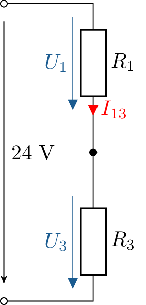
\(U_3 = 24 \, \mathrm {V} \cdot \frac {R_3}{R1+R_3} = 14.4 \, \mathrm {V}\)
Alternativ:
\(U_3 = R_3 \cdot I_{13} = 14,4 \, \mathrm {V}\)
\(U_1\) kann beispielsweise mittels Maschenumlauf ermittelt werden, Spannungsteiler oder Ohm´sches Gesetz
wären aber auch möglich:
\(U_1 = U_0 - U_3 = 24 \, \mathrm {V} - 14,4 \, \mathrm {V} = 9,6 \, \mathrm {V}\)
\(U_2 = R_3 \cdot I_{24} = 12 \, \mathrm {V}\)
\(U_4 = R_3 \cdot I_{24} = 12 \, \mathrm {V}\)
Zur Bestimmung der Spannung \(U_\mathrm {AB}\) werden Maschen in das Ersatzschaltbild eingezeichnet:
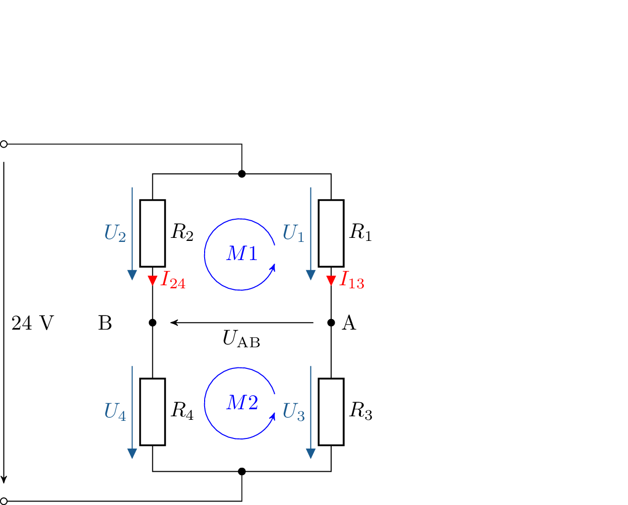
\(M_1: U_2 - U_\mathrm {AB} - U_ 1 = 0\)
\(\rightarrow U_\mathrm {AB} = U_2 - U_1 = 12 \, \mathrm {V} - 9,6 \, \mathrm {V} = 2,4 \, \mathrm {V}\)
Kontrolle mit Masche \(M2\):
\(M2: U_\mathrm {AB} + U_4 - U_2 = 0\)
\(\rightarrow U_\mathrm {AB} = U_3 - U_4 = 14,4 \, \mathrm {V} - 12 \, \mathrm {V} = 2,4 \mathrm {V}\)
Es muss also gelten: \(U_\mathrm {AB} = 0 \, \mathrm {V}\)
Auf \(M1\) bezogen bedeutet dies: \(U_1 = U_2 \rightarrow I_{13} \cdot R_1 = I_{24} \cdot R_2\)
Umgestellt nach \(I_{24}\) ergibt sich: \(I_{24} = I_{13} \cdot \frac {R_1}{R_2}\)
Auf \(M2\) bezogen bedeutet dies: \(U_3 = U_4 \rightarrow I_{13} \cdot R_3 = I_{24} \cdot R_4\)
Durch Einsetzen des Ausdruckes für \(I_{24}\) aus \(M1\) in die Gleichungen von \(M2\) lässt sich \(I_{24}\) eliminieren und das
Gleichungssystem lösen.
\(\rightarrow I_{13} \cdot R_3 = I_{13} \cdot \frac {R_1 \cdot R_4}{R_3}\)
\(\rightarrow \frac {R_1}{R_3} = \frac {R_2}{R_4}\)
Gegeben ist die dargestellte Schaltung aus den drei Widerständen \(R_1, R_2\) und \(R_3\) und den beiden Quellen \(U_{\mathrm {Q}}\) und \(I_{\mathrm {Q}}\).
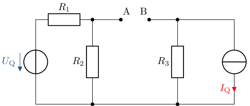
Zum bestimmen des Innenwiderstandes:
\( R_\mathrm {i,AB}= R_3 + \frac {R_1 \cdot R_2}{R_1 + R_2}\)
Zur Bestimmung der Leerlaufspannung oft sinnvoll: Stromquelle in Spannungsquelle umrechnen:
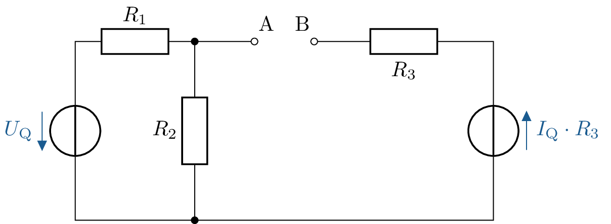
\(I_\mathrm {R3} = 0 \rightarrow U_\mathrm {R3} = 0\)
\(U_\mathrm {AB,L} = U_\mathrm {Q} \cdot \frac {R_2}{R_1+R_2} + I_\mathrm {Q} \cdot R_3\)
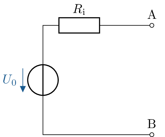
\(U_0 = U_\mathrm {AB,L} = U_\mathrm {Q} \cdot \frac {R_2}{R_1+R_2} + I_\mathrm {Q} \cdot R_3\)
\( R_\mathrm {i} = R_\mathrm {i,AB}= R_3 + \frac {R_1 \cdot R_2}{R_1 + R_2}\)
\(P_\mathrm {V} = P_1 + P_2 + P_3 = U_\mathrm {R1} \cdot I_1 + U_\mathrm {R2} \cdot I_2 + U_\mathrm {R3} \cdot I_3\)
\(= U_\mathrm {Q} \cdot \frac {R_1}{R_1+R_2} \cdot \frac {U_\mathrm {Q}}{R_1+R_2} +U_\mathrm {Q} \cdot \frac {R_2}{R_1+R_2} \cdot \frac {U_\mathrm {Q}}{R_1+R_2} + R_3 \cdot I_\mathrm {Q} \cdot I_\mathrm {Q} \)
\(= U_\mathrm {Q}^2 \cdot \frac {R_1}{(R_1+R_2)^2} + U_\mathrm {Q}^2 \cdot \frac {R_2}{(R_1+R_2)^2} + I_\mathrm {Q}^2 \cdot R_3 = \frac {U_\mathrm {Q}^2}{R_1+R_2} +I_\mathrm {Q}^2 \cdot R_3 \)
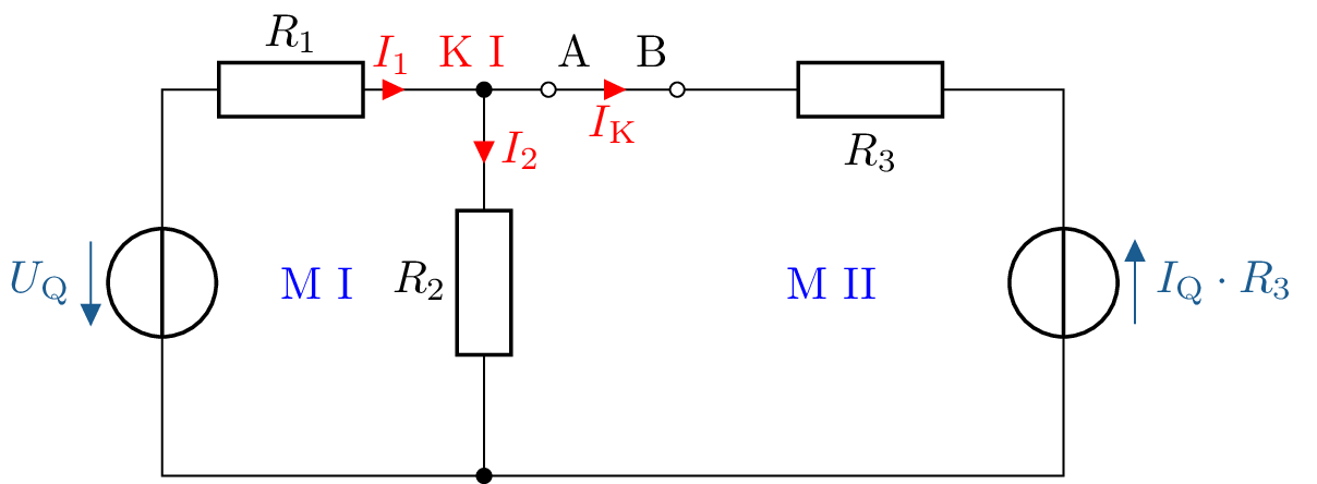
MI: \(R_1 \cdot I_1\) + \(R_2 \cdot I_2\) - \(U_0\) = 0
MII: \(- R_2 \cdot I_2 \) + \(R_3 \cdot I_\mathrm {K}\) - \(I_\mathrm {Q} \cdot R_3\) = 0
KI: \(I_1\) - \(I_2\) - \(I_\mathrm {K}\) = 0
3 Gleichungen, 3 Unbekannte \(\rightarrow \) Lösung über beispielsweise über Gauss-Algorithmus möglich.
Einfacher:
ESB aus c)
\(U_0 = U_\mathrm {AB,L} = U_\mathrm {Q} \cdot \frac {R_2}{R_1+R_2} + I_\mathrm {Q} \cdot R_3\)
\( R_\mathrm {i} = R_\mathrm {i,AB}= R_3 + \frac {R_1 \cdot R_2}{R_1 + R_2}\)
\(\rightarrow I_\mathrm {K} = \frac {U_0}{R_\mathrm {i}}= \frac {U_\mathrm {Q}\cdot R_2 + I_\mathrm {Q} \cdot R_3 \cdot (R_1+R_2)}{R_1 \cdot R_2 + R_3 \cdot (R_1+R_2)} \)
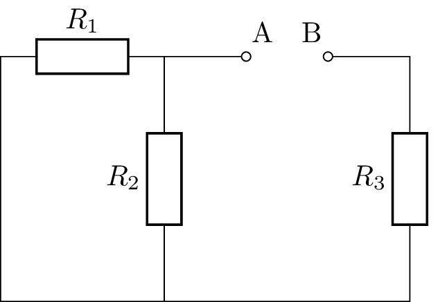
Aus c), Widerstand \(R\) eingefügt
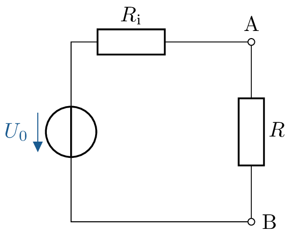
\(R_\mathrm {i} = \frac {R \cdot R}{R + R} + R= \frac {1}{2} \cdot R + R = \frac {3}{2} \cdot R\)
Aus d): \(U_0 = U_\mathrm {Q} \cdot \frac {R}{R+R} + R \cdot I_\mathrm {Q} = \frac {1}{2} U_\mathrm {Q} + R \cdot I_\mathrm {Q}\)
Spannungsteiler:
\(U_\mathrm {AB} = U_0 \cdot \frac {R}{2,5 \cdot R}\)
\( = 0,4 \cdot U_0 = U_\mathrm {Q} \cdot 0,5 \cdot 0,4 + I_\mathrm {Q} \cdot R \cdot 0,4 = 0,2 \cdot U_\mathrm {Q} + 0,4 \cdot R \cdot I_\mathrm {Q}\)
Gegeben seien die zwei abgebildeten Netzwerke eines Generators und eines Verbrauchers. Der Generator
besteht aus zwei parallel geschalteten, realen Quellen mit den idealen Spannungsquellen \(U_{01}\) und \(U_{02}\)
sowie den Innenwiderständen \(R_{i1}\) und \(R_{i2}\). Der Verbraucher besteht nur aus dem Lastwiderstand \(R_V\).

Für die weiteren Teilaufgaben soll der Generator mit dem Verbraucher \(R_V\) belastet werden. Es gelte weiter \(U_0 = U_{01} = U_{02}\) und \(R_i = R_{i1} = R_{i2}\).
Maschen- und Knotengleichungen:
\[ \sum _k U_k = 0: 0 = U_{01} - R_{i1} I_1 - U_{02} + R_{i2} I_2 \]
\[ \sum _k I_k = 0: 0 = I_1 + I_2 \;\Rightarrow \; I_1 = -I_2 \]
Ströme \(I_1\) und \(I_2\):
\[ \Rightarrow \; U_{01} - U_{02} = (R_{i1} + R_{i2}) I_1 = 0 \]
\[ \Rightarrow \; I_1 = -I_2 = 0 \]
Leistung \(P_G\):
\[ \Rightarrow \; P_G = R_{i1} I_1^2 + R_{i2} I_2^2 \text {mit } R_i = R_{i1} = R_{i2} \text { und } I_1 = -I_2 = 0 \]
\[ = 2 R_i I_1^2 = 0 \]
Klemmenspannung \(U_G\):
\[ \Rightarrow \; U_G = U_{01} - R_{i1} I_1 \text {mit } I_1 = 0 \]
\[ = U_0 \text {mit } U_0 = U_{01} \]
\[ \Rightarrow \; U_{01} - U_{02} = (1{,}1 - 1)\, U_0 = 2 R_i I_1 \]
\[ \Rightarrow \; I_1 = -I_2 = \frac {0{,}1\, U_0}{2 R_i} = \frac {1}{20 R_i}\, U_0 \]
Leistung \(P_G\):
\[ \Rightarrow \; P_G = 2 R_i \left ( \frac {1}{20 R_i} U_0 \right )^2 \]
\[ = \frac {1}{200 R_i}\, U_0^2 \]
Klemmenspannung \(U_G\):
\[ \Rightarrow \; U_G = U_{01} - R_{i1} I_1 \]
\[ = 1{,}1\, U_0 - R_i \frac {1}{20 R_i} U_0 \text {mit } R_{i1} = R_i \]
\[ = 1{,}05\, U_0 \]
Für die weiteren Teilaufgaben soll der Generator mit dem Verbraucher \(R_V\) belastet werden. Es gelte weiter \(U_0 = U_{01} = U_{02}\) und \(R_i = R_{i1} = R_{i2}\).

Anschließend die beiden realen Stromquellen zusammenfassen und zu einer realen Spannungsquelle umrechnen:

\[ I_{01} = \frac {U_{01}}{R_{i1}} = \frac {U_0}{R_i} \]
\[ I_{02} = \frac {U_{02}}{R_{i2}} = \frac {U_0}{R_i} \]
Zusammenfassen von Quellen und Widerständen:
\[ I_{0,\mathrm {ges}} = I_{01} + I_{02} = 2\,\frac {U_0}{R_i} \]
\[ R_{i,\mathrm {ges}} = \frac {R_{i1} R_{i2}}{R_{i1} + R_{i2}} = \frac {R_i^2}{2 R_i} = \frac {1}{2} R_i \]
Stromquelle in äquivalente Spannungsquelle umwandeln:
\[ U_{0,\mathrm {ges}} = R_{i,\mathrm {ges}}\, I_{0,\mathrm {ges}} = \frac {1}{2} R_i \, 2 \frac {U_0}{R_i} = U_0 \]
Generatorspannung \(U_G\):
\[ U_G = \frac {R_V}{R_V + R_{i,\mathrm {ges}}}\, U_{0,\mathrm {ges}} \]
\[ = \frac {R_V}{R_V + \tfrac {1}{2} R_i}\, U_0 \]
\[ = \frac {2 R_V}{2 R_V + R_i}\, U_0 \]
\[ P_G = \frac {1}{R_{i,\mathrm {ges}}}\,\bigl (U_{0,\mathrm {ges}} - U_G\bigr )^2 \]
\[ = \frac {2}{R_i} \left ( U_0 - \frac {2 R_V}{2 R_V + R_i}\, U_0 \right )^2 \]
\[ = \frac {2}{R_i} \left ( 1 - \frac {2 R_V}{2 R_V + R_i} \right )^2 U_0^2 \]
\[ P_V = \frac {1}{R_V}\, U_G^2 \]
\[ = \frac {1}{R_V} \left ( \frac {2 R_V}{2 R_V + R_i} \right )^2 U_0^2 \]

Aufgaben
...